
Visible light photocatalysis apparatus

A visible light and photocatalytic technology, applied in general water supply saving, chemical instruments and methods, chemical/physical processes, etc., can solve the problems of high processing cost and high device cost, and achieve the effect of low cost of use

Inactive Publication Date: 2016-05-25
徐志兵
View PDF4 Cites 2 Cited by
  • Summary
  • Abstract
  • Description
  • Claims
  • Application Information

AI Technical Summary

Problems solved by technology

Because the device uses electricity as the energy source of the LED flat panel lamp, and uses ozone oxidation and photocatalysis to treat wastewater simultaneously, there are problems such as high treatment cost and high device cost.

Method used


Image

  • Visible light photocatalysis apparatus

Examples


Embodiment 1

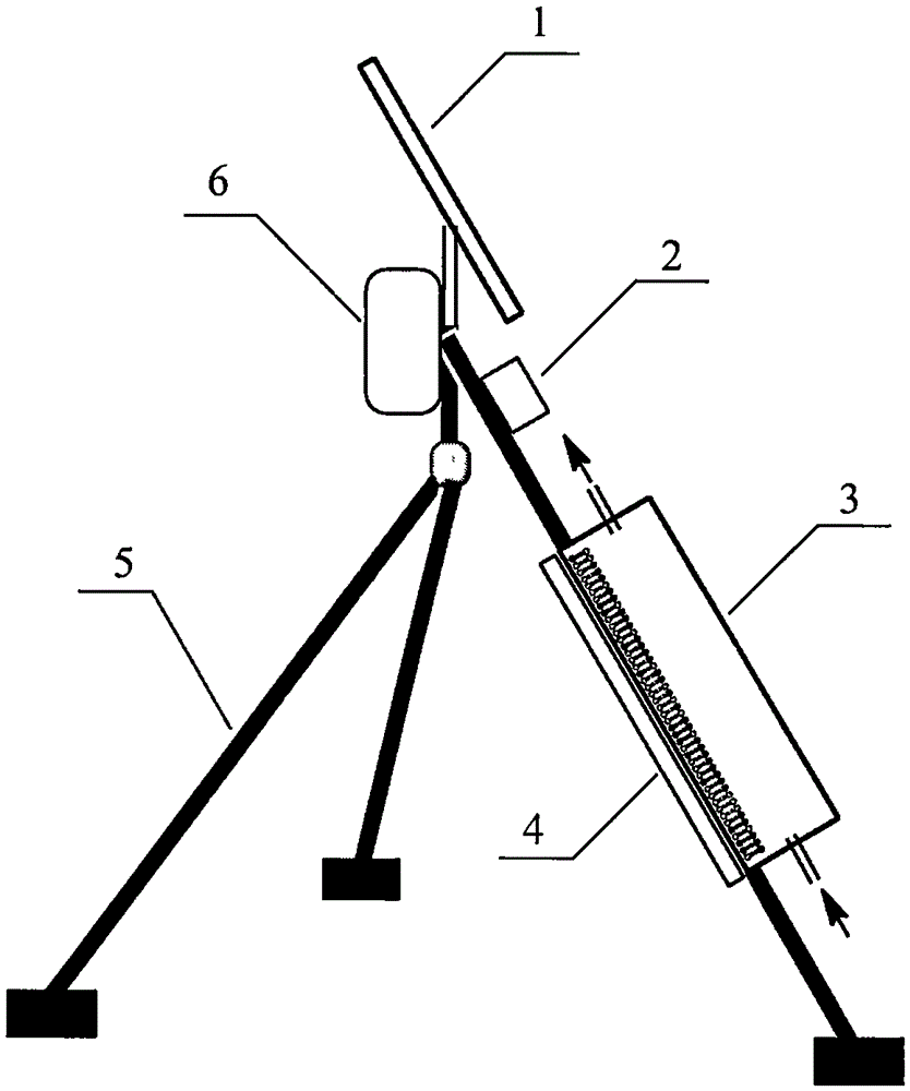
[0010] Visible light photocatalytic device to treat domestic sewage: such as figure 1 As shown, the photoreactor 3 is fixed on the support 5, and there is granular Ag / TiO in the photoreactor 3 2 The photocatalyst and domestic sewage enter the photoreactor 3 for reaction. The solar panel 1 can use sunlight to charge the storage battery 6 , and the storage battery 6 can provide power for the light intensity control system 2 and the self-contained light source 4 . When the sunlight is strong, the photoreactor 3 uses sunlight as the photocatalytic light; when there is no sunlight or insufficient sunlight, the light intensity control system 2 automatically turns on when the sunlight is lower than the set light intensity value. The self-contained light source 4 is switched on and off, and the self-contained light source 4 is used to provide light for photocatalysis. Under the action of light and catalyst, most of the organic pollutants are oxidized and decomposed, and the domestic...

Embodiment 2

[0012] Visible light photocatalytic device to treat exhaust gas: such as figure 1 As shown, the photoreactor 3 is fixed on the support 5, and there is a loaded Ag / TiO in the photoreactor 3 2 / Activated carbon composite photocatalyst, the exhaust gas containing a trace amount of formaldehyde enters the photoreactor 3 for reaction. The solar panel 1 can use sunlight to charge the storage battery 6 , and the storage battery 6 can provide power for the light intensity control system 2 and the self-contained light source 4 . When the sunlight is strong, the photoreactor 3 uses sunlight as the photocatalytic light; when there is no sunlight or insufficient sunlight, the light intensity control system 2 automatically turns on when the sunlight is lower than the set light intensity value. The self-contained light source 4 is switched on and off, and the self-contained light source 4 is used to provide light for photocatalysis. Under the irradiation of light and the action of catalys...


PUM


Abstract

A visible light photocatalysis apparatus is composed of a solar cell panel, a storage cell, a light reactor, a light intensity control system, a self-contained light source and a support. The solar cell panel uses the storage cell to charge, and the storage cell can provide power for the light intensity control system and the self-contained light source; the light intensity value of the light intensity control system can be set, the self-contained light source is automatically powered on when the light intensity of sunshine is smaller than a preset value in order to provide sunshine for the light reactor, and when the light intensity of sunshine is greater than a preset value, the self-contained light source is powered off, and the sunshine is used as light reactor irradiation light; and a photocatalyst is arranged in the light reactor, the shell of the light reactor adopts a light transmission material and is fixed on the support, wastewater or exhaust gas is purified in the light reactor, and the purified wastewater or exhaust gas flows out of the light reactor. The visible light photocatalysis apparatus fully uses sunshine as a photoreactor light source, and uses the sunshine to charge the storage cell in order to provide the power supply used by the apparatus, and has the characteristics of energy saving, low use cost and automatic running, so the apparatus can be used in fields of factories and town wastewater or exhaust gas treatment.

Description

(1) Technical field: [0001] The patent of the present invention relates to a device for purification and treatment of organic pollutants, in particular to a device for photocatalytic purification and treatment of organic pollutants. (two) background technology: [0002] In recent years, with the development of my country's economy and society, the pollution of waste water or waste gas to the environment has become more and more serious. Traditional waste water and waste gas treatment methods have problems such as high treatment costs and low treatment efficiency. Therefore, we are looking for excellent, efficient and low-cost Pollution control methods have always been a hot topic of concern. Photocatalytic technology is to use catalytic materials such as titanium dioxide to catalyze and degrade organic pollutants in wastewater and waste gas under normal temperature and pressure and various light irradiations, and finally become non-polluting substances. As a new type of envi...

Claims


Application Information

Patent Timeline
Patent Type & Authority Applications(China)
IPC IPC(8): B01D53/86B01D53/72C02F1/30C02F1/72B01J19/12B01J8/00
CPCY02A20/212Y02W10/37
Inventor 徐志兵宋磊黄如全
Owner 徐志兵
Learn More