Eureka AIR delivers breakthrough ideas for toughest innovation challenges, trusted by R&D personnel around the world.

Composite snap-in pile retaining wall construction method and a composite snap-in pile retaining wall structure

A construction method and retaining wall technology, applied to sheet pile walls, underwater structures, foundation structure engineering, etc., can solve problems such as difficulty in meeting the requirements of design and construction units, high support cost, and long construction period, and achieve Improve the overturning capacity of retaining soil and overturn protection, the quality of the pile body is reliable, and the effect of reducing construction links

Inactive Publication Date: 2016-05-18
刘献刚
View PDF6 Cites 1 Cited by
  • Summary
  • Abstract
  • Description
  • Claims
  • Application Information

AI Technical Summary

Problems solved by technology

However, this construction method is only suitable for above-ground water level or through artificial gravel, pebble layer, silt and other soft layers, and soil nailing needs to occupy a large underground space outside the pit.
2. Pile row support construction method: Although it has the advantages of simple construction machinery and technology, and adapts to a wide range of soil layers, it has the disadvantages of high cost, long construction period, and the need to set up waterproof tents to prevent seepage
3. Cement-soil gravity retaining wall construction method: it has the advantages of simple and easy construction equipment and technology, and reliable water-proof performance, but it still has a large amount of cement, which is uneconomical, and the structure occupies a large space. It is generally only suitable for soft soil foundation pits. The excavation depth does not exceed 7M, and the construction has a great impact on the surrounding environment.
4. Construction method of underground diaphragm wall: the wall has high rigidity and has dual functions of "soil retaining" and "water isolation". The deformation of the support structure is small, but there are many spoils and waste mud, the amount of cement and steel is large, and the cost is high. The shortcoming of long construction period, at the same time, it is easy to cause the tank wall to collapse and seepage when encountering the silt layer, and the wall and joints are also prone to water seepage
[0003] In short, the above conventional foundation pit support construction methods are difficult to meet the design and construction requirements due to the high cost of support, long construction period, or the constraints of site conditions (groundwater level, surrounding building foundations, and inability to drain outside the wall, etc.). The requirements of the construction unit

Method used


Image

  • Composite snap-in pile retaining wall construction method and a composite snap-in pile retaining wall structure
  • Composite snap-in pile retaining wall construction method and a composite snap-in pile retaining wall structure
  • Composite snap-in pile retaining wall construction method and a composite snap-in pile retaining wall structure

Examples


Embodiment 1

[0037] The construction method of composite snap pile retaining wall of the present invention comprises the following steps:

[0038] a. Level the site, set out the line to determine the pile position,

[0039] b. Construct cement-soil mixing piles, and arrange several piles interlocking with each other;

[0040] c. Level the site, check and set out the line, and determine the pile position of the anchor cable bored pile; apply the anchor cable bored pile; use the long spiral drilling process to cut the cement-soil mixing pile on both sides to form holes; press again poured concrete piles;

[0041] d. Fix the prestressed anchor cable in the reinforcement cage of the anchor cable borehole press grouting pile according to the design requirements, and then vibrate the reinforcement cage into the anchor cable borehole press grout pile pile body;

[0042] e. Carry out prestressed anchor cable installation construction;

[0043] f. Pour concrete on the top of the pile to press th...

Embodiment 2

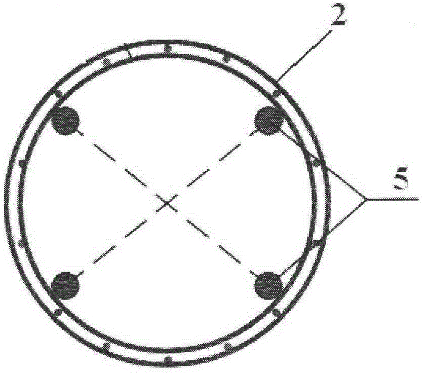
[0049] Such as figure 1 As shown, a kind of compound snap-in pile retaining wall structure of the present invention comprises: several cement-soil mixing pile bodies 1; At least one cement-soil mixing pile body 1 is arranged between the 2 press-grouting pile bodies; the anchor cable drilled press-fill pile body 2 and the cement-soil mixing pile body 1 are interlocked and arranged; as figure 2 and 3 As shown, the anchor cable bored pile body 2 includes a top beam 3, and the top beam 3 is arranged on the top of the anchor cable bored pile body 2; the anchor cable bored pile body 2 is provided with a reinforcement cage 4 and a prestressed anchor cable 5, wherein one end of the prestressed anchor cable 5 is fixed on the end of the reinforcement cage 4 close to the bottom end of the anchor cable drilled pile body 2, The other end of the prestressed anchor cable 5 is anchored to the capping beam 3 through an anchor 6 .

[0050] As a preferred embodiment, the composite snap-in pi...


PUM


Abstract

The invention relates to a composite snap-in pile retaining wall construction method which comprises the following steps: a. leveling up a field and paying off to determine a pile location; b. constructing cemented soil mixing piles, and arranging a plurality of piles in a mutually engaging way, preferably, 4-8 piles are arranged; c. leveling up the field, re-checking and paying off to determine the location of an anchor rope drilling press-grouting pile; constructing the anchor rope drilling press-grouting pile, cutting cemented soil mixing piles at two sides by adopting a long auger drilling process to form holes, and pressing and grouting the concrete piles; d. fixing a pre-stressed anchor rope in a reinforcement cage of the anchor rope drilling press-grouting pile according to design requirements, and then inserting the reinforcement cage into the anchor rope drilling press-grouting pile in a vibrating way; e. carrying out pre-stressed anchor rope insertion construction; f. pouring and pounding concrete top beams on pile tops; g. after the strength of the pile concrete, the cemented soil and anchor rod mortar meets design age requirements, implementing tension construction of a pre-stressed anchor rope and a pre-stressed anchor rod; h. excavating pit earthwork, wherein when second layer and third layer of anchor rods exist, excavation needs to be performed in layers and cross beams and anchor rods at the lower layer are constructed in sequence; and i. excavating to reach pit bottom elevation.

Description

technical field [0001] The invention relates to a construction method for a retaining wall of composite snapping piles and a structure for retaining walls of composite snapping piles. Background technique [0002] At present, in the design and construction of foundation pit slope support in my country, construction schemes and construction methods are often used, such as soil nail wall, pile row, cement-soil gravity retaining wall, underground diaphragm wall, etc. 1. Soil nailing wall: This construction method has simple construction machinery and equipment, and the construction method is easy. Soil nails have a strong ability to penetrate the soil layer, can prevent groundwater and rainwater erosion and soil erosion, and are economical. However, this construction method is only applicable to above the groundwater level or through artificial gravel, pebble layers, silt and other soft layers, and soil nailing needs to occupy a large underground space outside the pit. 2. Pil...

Claims


Application Information

Patent Timeline
IPC IPC(8): E02D17/04E02D29/02E02D5/76E02D5/34
CPCE02D5/34E02D5/76E02D17/04E02D29/0233E02D29/0275E02D2600/30
Inventor 刘献刚付豫楹乐平刘斌熊新华
Owner 刘献刚
Why Eureka
Eureka Blog
Learn More