Double-regulation flow distribution type efficient separator

A separator and shunt-type technology, applied in the field of separators, can solve the problems of poor powder uniformity, poor adjustment effect of radial baffles, increased energy consumption, etc., achieve good powder uniformity at the outlet, solve poor adjustment performance, increase The effect of regulatory capacity

Active Publication Date: 2016-05-18
君联益能(北京)科技有限公司
View PDF14 Cites 0 Cited by
  • Summary
  • Abstract
  • Description
  • Claims
  • Application Information

AI Technical Summary

Problems solved by technology

Due to the poor adjustment effect of the radial baffle, the separator with this static structure leads to poor powder fineness and uniformity, so that the factory often cannot meet the requirements of high-quality powder and appropriate output at the same time, which affects the economy of the factory
In order to solve the deficiencies of the separator of the static structure, there is also a dynamic separator in the prior art, which solves the defects of the separator of the static structure by adding moving parts and motors and its control system, but due to the increase of the moving parts And the motor and its control system, there are many problems in the process of use, such as increased vibration of Limao, increased energy consumption, increased pressure drop, large maintenance, etc., which seriously affect the safety of the milling system in the factory , reliability and economy
[0005] In summary, the separators used in vertical mills in the prior art have disadvantages such as low separation efficiency, high outlet powder fineness, poor powder uniformity, high pressure drop, and high energy consumption.

Method used


Image

  • Double-regulation flow distribution type efficient separator
  • Double-regulation flow distribution type efficient separator
  • Double-regulation flow distribution type efficient separator

Examples


specific Embodiment 1

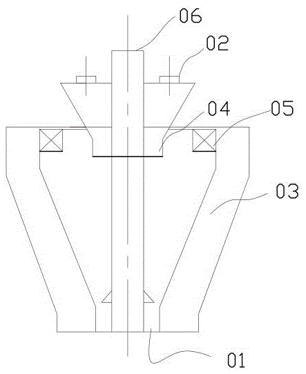
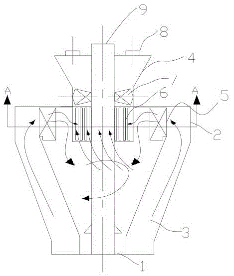
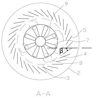
[0024] combined with figure 2 to attach Figure 5 , a dual-adjustment split-flow high-efficiency separator, which includes air powder inlet 1, separator shell 2, separator inner cone 3, distributor 4, radial vanes 5, axial vanes 7, air powder outlet 8 and inlet Material pipe 9; the air powder inlet 1 is located at the small-diameter end of the separator inner cone 3; the separator inner cone 3 is installed in the separator housing 2; the described feed pipe 9 is inserted into the separator Inside the inner cone 3; the distributor 4 is sleeved on the feed pipe 9, the distributor 4 is funnel-shaped, and the vertical section at the bottom of the distributor 4 is provided with several slit structures 6; The slit structure 6 is distributed along the circumference, and the slit of the slit structure extends along the axial direction of the distributor 4; the radial vane 5 is located at the large-diameter end of the separator inner cone 3, and the radial vane 5 is located along the...

specific Embodiment 2

[0025] further combined with Figure 6 , a dual-adjustment split-flow high-efficiency separator, which includes air powder inlet 1, separator shell 2, separator inner cone 3, distributor 4, radial vanes 5, axial vanes 7, air powder outlet 8 and inlet Material pipe 9; the air powder inlet 1 is located at the small-diameter end of the separator inner cone 3; the separator inner cone 3 is installed in the separator housing 2; the described feed pipe 9 is inserted into the separator Inside the inner cone 3; the distributor 4 is sleeved on the feed pipe 9, the distributor 4 is funnel-shaped, and the vertical section at the bottom of the distributor 4 is provided with several slit structures 6; The slit structure 6 is distributed along the circumference, and the slit of the slit structure extends along the axial direction of the distributor 4; the radial vane 5 is located at the large-diameter end of the separator inner cone 3, and the radial vane 5 is located along the separator T...


PUM


Abstract

The invention provides a double-regulation flow distribution type efficient separator. According to the double-regulation flow distribution type efficient separator, the pressure drop is low, the separating efficiency is high, the uniformity of outlet powder is good, and the regulation performance is good. The double-regulation flow distribution type efficient separator comprises a pulverized coal inlet, a separator shell, a separator inner cone, a distributor, radial vanes, axial vanes, a pulverized coal outlet and a feeding pipe. The pulverized coal inlet is located in the small-diameter end of the separator inner cone. The separator inner cone is installed in the separator shell. The feeding pipe is inserted in the separator inner cone. The feeding pipe is sleeved with the distributor. The distributor is in a funnel shape. Open seam structures are formed in the vertical lower section of the distributor and distributed along the circumference. Seams of the open seam structures extend in the axis direction of the distributor. The radial vanes are located at the large-diameter end of the separator inner cone and distributed along an annular belt between the inner wall of the separator inner cone and the outer wall of the distributor in the circumferential direction. The axial vanes are installed on the outer wall of the feeding pipe and located in the distributor. The pulverized coal outlet is located in the upper end of the distributor. The number of the axial vanes is larger than one.

Description

technical field [0001] The invention relates to a separator for a vertical mill, in particular to a double-adjustment split-flow high-efficiency separator. Background technique [0002] Vertical mill is an ideal large-scale grinding equipment, which is widely used in cement, electric power, metallurgy, chemical industry, non-metallic minerals and other industries. It integrates crushing, drying, grinding, grading and conveying, and has high production efficiency. It can grind block, granular and powder raw materials into required powder materials. The vertical mill is an indispensable and important equipment in the grinding industry. The vertical mill is suitable for pulverization and grinding of medium-hard materials such as bituminous coal and lean coal. It has two sets of relatively moving grinding parts. Under the action of spring force, hydraulic pressure or other external forces, the raw coal in between is squeezed and ground, and finally broken into powder; through t...

Claims


Application Information

Patent Timeline
IPC IPC(8): B07B7/083
CPCB07B7/083
Inventor 朱琳枫
Owner 君联益能(北京)科技有限公司
Why Eureka
Try Eureka