Swirling-flow float valve tower plate

A float valve tray and float valve technology, which is applied in the fields of purification, rectification and absorption, can solve the problems that the float valve tray is easy to block, there is a liquid stagnation area, and the gas distribution is uneven, so as to improve the flux and efficiency , reduce the liquid surface gradient, reduce the effect of resistance

Inactive Publication Date: 2016-05-18
CHINA PETROLEUM & CHEM CORP +1
View PDF9 Cites 2 Cited by
  • Summary
  • Abstract
  • Description
  • Claims
  • Application Information

AI Technical Summary

Problems solved by technology

[0004] The technical problem that the present invention intends to solve is that the existing float valve trays have problems such as easy blockage, large liquid level gradient on the tray, uneven gas distribution, liquid stagnation area, and low efficiency of the tray; Cyclone valve tray with self-cleaning function, stable liquid flow on the tray, small liquid level gradient, small tray pressure drop, high mass transfer efficiency, and strong anti-clogging ability

Method used


Image

  • Swirling-flow float valve tower plate
  • Swirling-flow float valve tower plate
  • Swirling-flow float valve tower plate

Examples


Embodiment 1

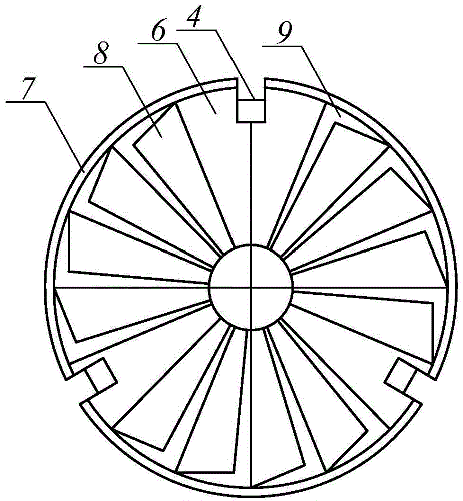
[0031] Such as Figure 1-3 As shown, the swirl valve tray of the present invention is made up of a tray (1), a swirl valve (2), and a valve hole (3); the tray (1) is punched with a valve hole (3) , the swirl float valve (2) is installed on the valve hole (3); the swirl sheet (7) is installed on the valve face (6) of the swirl float valve (2); there are valve legs (4) and The valve foot (5), the valve foot (5) is connected to the valve face (6) through the valve leg (4).

[0032] Composition of shift gas (vol%): CO 2 is 43.5, CO is 0.323, H 2 55.23, H 2 S is 0.188, HCN is 0.002, N 2 is 0.757; the temperature of the absorption tower is -40~-60°C, the pressure is 2.4MPa, and the gas-liquid ratio is 0.565m 3 (synthesis gas): 1kg (methanol)

[0033] For the swirl float valve, the number of swirl sheets on the valve surface (6) is 4 pieces; there is an included angle between the valve surface and the valve hole is α=30°; there are three valve legs under the valve surface, and ...

Embodiment 2

[0035] According to the conditions and steps described in Example 1, for the swirl valve tray, the number of swirl sheets on the valve surface (6) is 20; there is an included angle between the valve surface and the valve hole as α= 60°; there are three valve legs under the valve surface, and the height of the valve legs is h=40mm. The valve surface (6) is circular, the swirl sheet (8) and the valve hole (9) are fan-shaped, and the swirl float valve (2) is a floating type. The total sulfur of the purified syngas is less than lppm, CO 2 Less than 20ppm meets the technological requirements of the subsequent synthesis unit for the synthesis gas purification index.

Embodiment 3

[0037] According to the conditions and steps described in Example 1, for the swirl valve tray, the number of swirl sheets on the valve surface (6) is 12; there is an included angle between the valve surface and the valve hole as α= 45°; there are three valve legs under the valve surface, and the height of the valve legs is h=10mm. The valve surface (6) is circular, the swirl sheet (8) and the valve hole (9) are fan-shaped, and the swirl float valve (2) is fixed. The total sulfur of the purified syngas is less than lppm, CO 2 Less than 20ppm meets the technological requirements of the subsequent synthesis unit for the synthesis gas purification index.


PUM


Abstract

The invention relates to an internal component of oil-refining and chemical equipment, specifically to a swirling-flow float valve tower plate. The swirling-flow float valve tower plate comprises a valve face, a swirling-flow hole, a supporting angle, valve legs, valve feet, a tower plate and a gas guiding hole. According to the invention, gas enters the tower plate from the valve hole and is firstly dispersed by the valve hole, wherein part of the gas ejects from the swirling-flow hole arranged on the valve face and forms small-size gas bubbles after contacting with liquid; since the action of a swirling-flow field strengthens mass transfer between gas and liquid phases above the valve face, treatment capacity of the tower is greatly improved; meanwhile, the swirling-flow float valve tower plate has the advantages of self-cleaning capacity, small gradient of a liquid level on the tower plate, uniform distribution of the gas, no liquid-stagnation zone, high efficiency of the tower plate, large treatment capacity, etc., and can be extensively applied in unit operations like mass transfer and heat transfer of gas-liquid two phases and gas-liquid-solid three phases like gas purification, rectification, absorption and dust-removal.

Description

technical field [0001] The invention relates to the technical field of gas-liquid contact mass transfer equipment in oil refining, petrochemical and chemical industries, especially purification, rectification and absorption. technical background [0002] The valve tray has the advantages of large production capacity, large operating flexibility, and high tray efficiency, and is one of the most widely used plate types. In the prior art, for example, application number 01200988.1, the patent application document titled "A Microdispersion Fixed Valve" discloses that it includes a tray and a valve surface, the valve surface is flushed out from the tray body, and the valve surface passes through the valve leg and the valve surface. The trays are connected, the valve surface is parallel to the tray, one or more tongues are punched on the valve surface, the tongues are parallel to the valve surface, and one end of the tongue is connected to the valve surface. The technical defects...

Claims


Application Information

Patent Timeline
Patent Type & Authority Applications(China)
IPC IPC(8): B01D3/18B01D3/20
Inventor 王清立陈亮钟思青郭艳姿张鸿翔王璐
Owner CHINA PETROLEUM & CHEM CORP
Why Eureka
Try Eureka