An integrated cascadable optical fiber receiver tuner module
A fiber optic receiver and tuner technology, which is applied in the direction of TV systems adapting to optical transmission, cable transmission adaptation, electrical components, etc., can solve the problem of affecting the TV reception effect of fiber optic set-top boxes, the fact that fiber optic set-top boxes cannot support cascading functions, increasing the production cost of set-top boxes and Volume and other issues, to avoid index and size matching problems, optimize circuit composition, and reduce the number of components
- Summary
- Abstract
- Description
- Claims
- Application Information
AI Technical Summary
Problems solved by technology
Method used
Image
Examples
no. 1 example
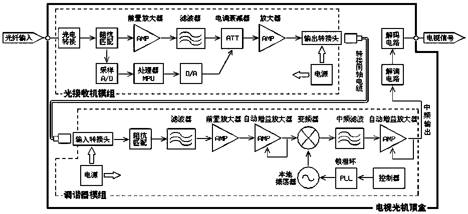
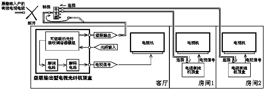
[0051] This embodiment includes a housing, a power supply, an optical receiver with adjustable amplification gain, and a tuner; the optical receiver, the tuner and the power supply are all packaged in the housing; inside the housing, the output end of the optical receiver It is connected with the input end of the tuner, and the power supply is used to supply power to the optical receiver and the tuner; the input end of the optical receiver and the output end of the tuner are all drawn from the casing; the output end of the tuner includes a cascaded signal lead terminal and IF signal output terminal.
[0052] Specifically, the optical receiver includes an optical fiber access end, a photoelectric conversion circuit, an impedance matching circuit, a preamplifier, a denoising filter and an adaptive signal enhancement circuit. The tuner includes an automatic gain amplifier 1, a power divider, a frequency converter, a local frequency generating circuit, an intermediate frequency fi...
no. 2 example
[0065] like figure 2 , the adaptive signal enhancement circuit in this embodiment includes a comparator, a two-stage amplifier and a two-to-one switch.
[0066] The signal output end of the denoising filter is connected to the first signal input end of the one-of-two switch on the one hand, and is also connected to the signal input end of the secondary amplifier on the other hand. The second signal input end is connected, and the signal output end of the two-choice switch is connected with the signal input end of the automatic gain amplifier 1 .
[0067] The second signal output terminal of the impedance matching circuit is also connected to the first input terminal of the comparator, the second input terminal of the comparator is connected to the reference reference electrical signal, and the output terminal of the comparator is connected to the control terminal of the two-to-one switch.
[0068] The comparator receives the second output signal voltage of the impedance matc...
PUM
 Abstract
Description
Claims
Application Information
 - R&D
- Intellectual Property
- Life Sciences
- Materials
- Tech Scout
- Unparalleled Data Quality
- Higher Quality Content
- 60% Fewer Hallucinations
Browse by: Latest US Patents, China's latest patents, Technical Efficacy Thesaurus, Application Domain, Technology Topic, Popular Technical Reports.
© 2025 PatSnap. All rights reserved.Legal|Privacy policy|Modern Slavery Act Transparency Statement|Sitemap|About US| Contact US: help@patsnap.com


