
Split type gear pump floating shaft sleeve combination piece and machining method thereof

A floating bushing and gear pump technology, applied in pump components, rotary piston/swing piston pump components, bearing components, etc., can solve the problems of difficult to guarantee the accuracy of parts, high processing rejection rate, and difficult to control product quality.

Inactive Publication Date: 2016-05-11
ZHEJIANG SF OILLESS BEARING
View PDF9 Cites 5 Cited by
  • Summary
  • Abstract
  • Description
  • Claims
  • Application Information

AI Technical Summary

Problems solved by technology

At present, the commonly used floating bushings are all processed in one piece, that is, the 8-shaped floating bushing is processed as a whole, and the 8-shaped upper and lower gear shaft holes and the two ends of the shaft hole are processed. When processing two gear shaft holes, secondary clamping is required. This figure-8 shape part is an irregular shape, and general-purpose fixtures cannot be used, and the figure-8 shape of the provided clamping parts is a non-machined surface. Secondary clamping It is difficult to guarantee the accuracy of the dimensional tolerance and position tolerance of the clamped parts. As a key part of the gear pump, its accuracy is very high, usually at level 5-6. Therefore, the reject rate of the traditional processing method is high, and the quality of the product has always been difficult to control.

Method used


Image

  • Split type gear pump floating shaft sleeve combination piece and machining method thereof
  • Split type gear pump floating shaft sleeve combination piece and machining method thereof
  • Split type gear pump floating shaft sleeve combination piece and machining method thereof

Examples


Embodiment Construction

[0016] The present invention will be further described below in conjunction with the accompanying drawings.

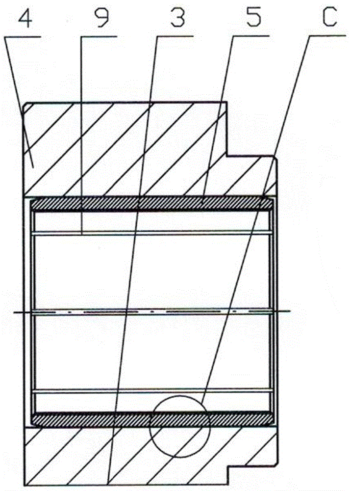
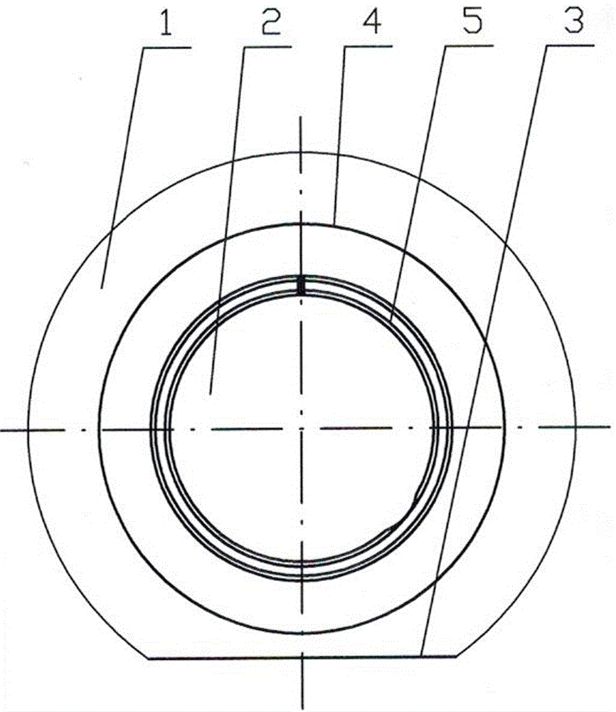
[0017] Figure 2 to Figure 4 It is a schematic diagram of the structure of the floating bushing assembly of the split gear pump. It can be seen from the figure that it includes a cylindrical bushing with a circular flange 1, and a plane 3 parallel to the shaft hole 2 is formed on the flange 1, and a floating bushing 4 is made into the floating bushing 4. A sliding bearing 5 made of a composite material roll is installed in the shaft hole 2. The sliding bearing 5 is followed by a steel sleeve 6 from the outside to the inside. The inner wall of the steel sleeve 6 is sintered with a copper alloy powder layer 7, and on the alloy copper powder layer 7 A polytetrafluoroethylene layer 8 is attached, and a spiral or 8-shaped oil groove 9 parallel to the axis is formed in the inner hole of the sliding bearing 5 . The planes 3 of the two floating bushings 4 are combined to for...


PUM


Abstract

The invention discloses a split type gear pump floating shaft sleeve combination piece and a machining method thereof. The split type gear pump floating shaft sleeve combination piece is good in machining process, and the product quality is easily guaranteed. The split type gear pump floating shaft sleeve combination piece comprises cylindrical shaft sleeves with circular flanges, a plane parallel to a shaft hole is manufactured on each flange, and floating shaft sleeves are manufactured; a sliding bearing made of composite materials is installed in the shaft hole of each floating shaft sleeve, a steel sleeve is arranged outside each sliding bearing, and copper alloyed powder layers are sintered on the inner walls of the steel sleeves; and Teflon layers are attached to the copper alloyed powder layers, and the planes of the two floating shaft sleeves are oppositely combined to form a floating shaft sleeve combination piece shaped like an Arabic numeral eight. According to the whole floating shaft sleeve combination piece shaped like the Arabic numeral eight, the two split floating shaft sleeves are combined, and therefore the machining accuracy and the production efficiency of the floating shaft sleeve are greatly improved.

Description

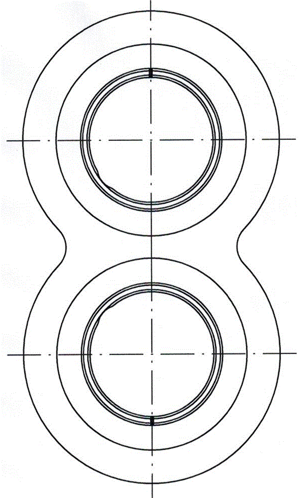
technical field [0001] The invention relates to parts of a gear pump, in particular to a split-type floating shaft sleeve assembly applied to a high-pressure gear pump and a processing method thereof. Background technique [0002] The gear pump is a commonly used part in the hydraulic system. It is a rotary pump that relies on the change and movement of the working volume formed between the pump body and the meshing gear to transport or pressurize the liquid. It consists of two meshing gears and an 8-shaped floating sleeve that is close to the two ends of the gears. figure 1 Shown consists of two enclosed spaces. The shafts on the two gears are inserted in the 8-shaped floating shaft sleeve holes. When the gear rotates, the volume of the space on the gear disengagement side becomes smaller and larger, forming a vacuum, which sucks the liquid, and the space volume on the gear meshing side changes from large to small, and squeezes the liquid into the pipeline to form a high-...

Claims


Application Information

Patent Timeline
Patent Type & Authority Applications(China)
IPC IPC(8): F16C35/02F16C33/20F16C33/00B23P15/00F04C15/00
CPCF16C35/02B23P15/003F04C15/00F16C33/00F16C33/201
Inventor 崔泉源
Owner ZHEJIANG SF OILLESS BEARING
Learn More