MIMO-SCMA system downlink design method based on STBC
A MIMO-SCMA and downlink technology, which is applied in the downlink design field of MIMO-SCMA system based on STBC, can solve the problems of SCMA technology bit error rate decrease and MIMO-OFDM technology is difficult to meet, and achieve bit error rate performance Enhanced effect
- Summary
- Abstract
- Description
- Claims
- Application Information
AI Technical Summary
Problems solved by technology
Method used
Image
Examples
specific Embodiment approach 1
[0019] Specific embodiment one: a kind of STBC-based MIMO-SCMA system downlink design method of this embodiment is specifically prepared according to the following steps:
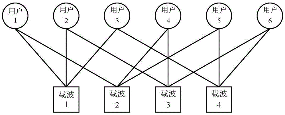
[0020] Step 1, the structure of the MIMO-SCMA (multi-antenna sparse code multiple access) transmitter is as follows figure 1 As shown, the base station is used to receive the information sent by the uplink And carry out STBC encoding (space-time block coding) to the information that uplink sends according to coding matrix G namely Alamouti space-time block coding; Obtain the information T of the uplink reception after coding W and T' W ; Use the two antennas of the base station to transmit T W and T' W ; Wherein, J is the number of users; j is the serial number of the user; the subscript W is the length of the information sent by the user; Information of length W sent for the uplink of the jth user;
[0021] Step 2. Put T in the channel W and T' W Converted to S after fading and mutual superpositi...
specific Embodiment approach 2
[0030] Specific implementation mode two: the difference between this implementation mode and specific implementation mode one is: in step one X W i = [ x w 1 j x w 2 j ... x w K j ] T ,
[0031] in, The length of W and the subcarrier K occupied by the uplink transmission of the jth user are information; the subscript K is the subcarrier occupied by the information sent by the user. Other steps and parameters are the same as those in Embodiment 1.
specific Embodiment approach 3
[0032] Specific implementation mode three: the difference between this implementation mode and specific implementation mode one or two is that in step two, T W and T' W Converted to S after fading and mutual superposition W and S' W Specifically:
[0033] Received by the user terminal after fading and mutual superposition in the channel; the received signal is expressed as:
[0034] S W S W ′ = Σ j = 1 J H T W T W ′ ...
PUM
 Abstract
Description
Claims
Application Information
 - R&D
- Intellectual Property
- Life Sciences
- Materials
- Tech Scout
- Unparalleled Data Quality
- Higher Quality Content
- 60% Fewer Hallucinations
Browse by: Latest US Patents, China's latest patents, Technical Efficacy Thesaurus, Application Domain, Technology Topic, Popular Technical Reports.
© 2025 PatSnap. All rights reserved.Legal|Privacy policy|Modern Slavery Act Transparency Statement|Sitemap|About US| Contact US: help@patsnap.com


