High-power density electric vehicle motor

A high power density, electric vehicle technology, applied in electric vehicles, motors, electric components, etc., can solve the problems of not too high motor winding efficiency, reduced stator winding efficiency, complex winding shape, etc., to achieve compact structure and strong bearing capacity. , the effect of high reliability

Inactive Publication Date: 2016-05-04
WANXIANG QIANCHAO TRANSMISSION SHAFT +1
View PDF6 Cites 2 Cited by
  • Summary
  • Abstract
  • Description
  • Claims
  • Application Information

AI Technical Summary

Problems solved by technology

[0007] The motor in CN103329410A needs to increase the power density again, and will be limited by the current density. In the design of this motor of YASA, there are many (typically such as 24) stator assemblies with concentrated windings. In this way, in the effective plane of the stator On the one hand, there is a stator magnetic conduction magnetic circuit and a stator winding section at the same time. The two structures compete with each other. On the other hand, the stator winding also has a winding efficiency problem, which is determined by the effective section of the winding and the actual circumference. Obviously, the more complicated the shape of the winding or the smaller the winding, the lower the efficiency of the winding. It is reflected from the design of the motor that the copper loss of the motor increases.
Of course, there are also some improvements in the structure of CN103283126A. The winding efficiency of the motor in the design is not too high, and most of the area in the middle of the winding is the non-effective area. At the same time, it can be seen from the structure of the rotor that the The surface-mounted permanent magnet structure, the magnetic circuit is a series structure, the magnetic field operating point of the motor cannot be too high, which is equivalent to reducing the winding efficiency of the stator

Method used


Image

  • High-power density electric vehicle motor
  • High-power density electric vehicle motor
  • High-power density electric vehicle motor

Examples


Embodiment Construction

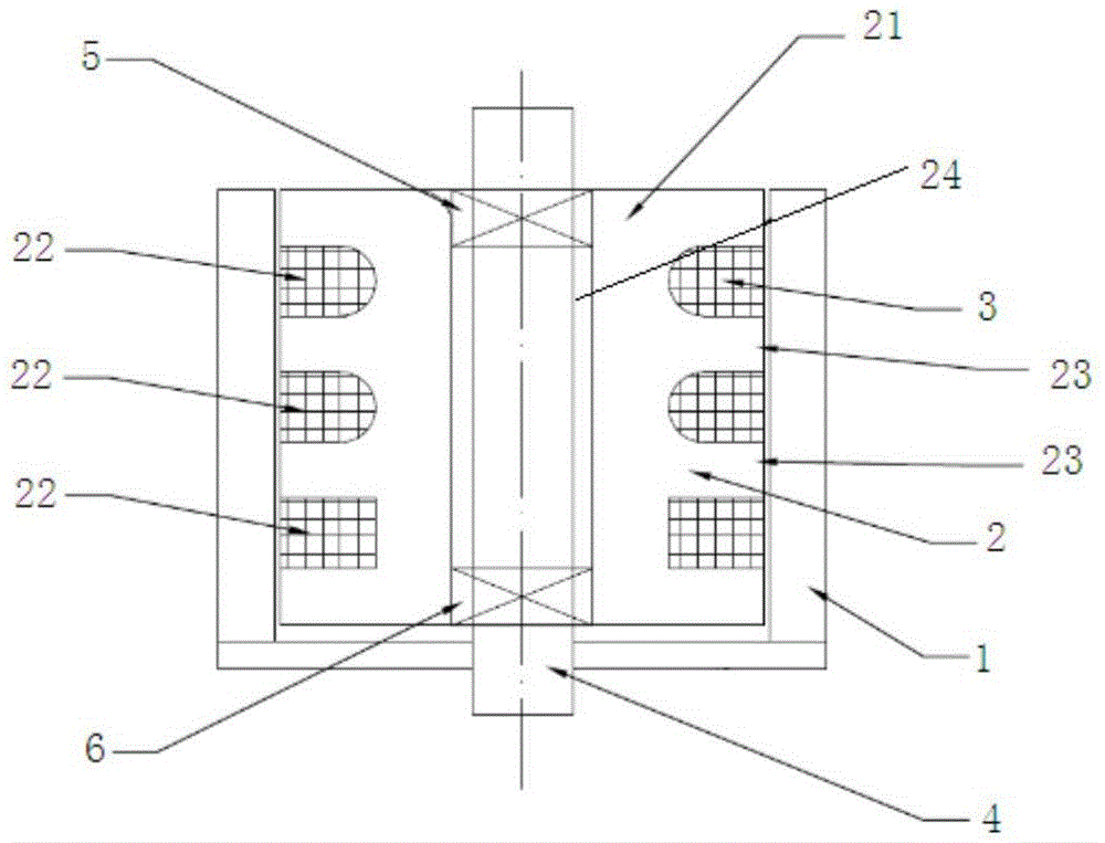
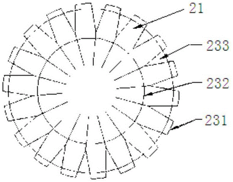
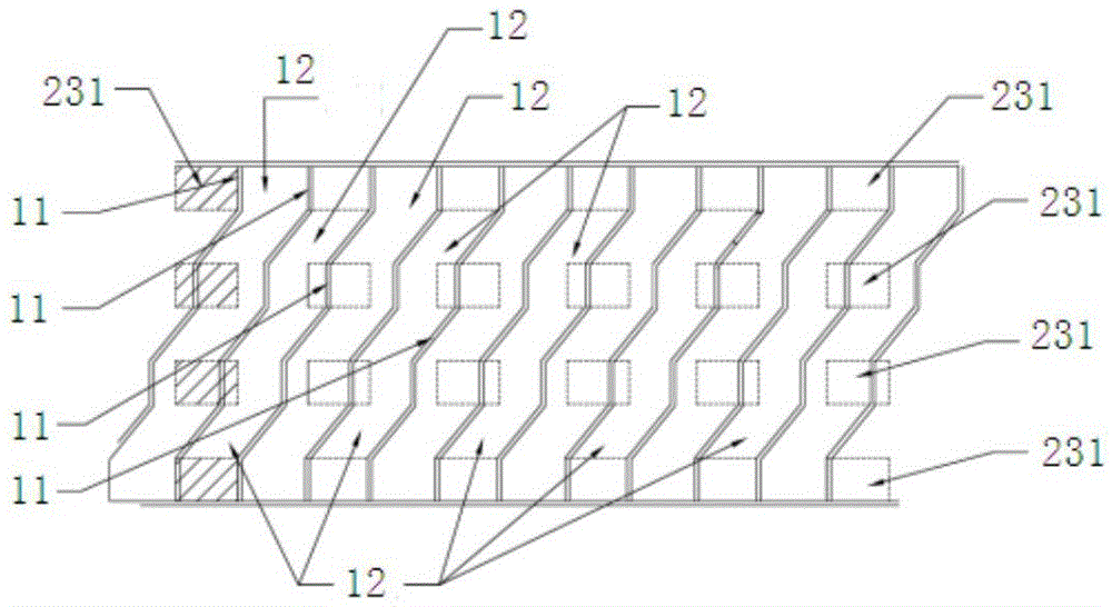
[0021] The present invention will be described in detail below in conjunction with accompanying drawing: Figures 1 to 3 As shown, the present invention is composed of a rotor 1 and a stator 2. The stator 2 is located in the rotor 1, and the circumferential area 21 of the stator 2 is provided with several stator slots 22 equally distributed up and down. The stator slots 22 An annular coil 3 is arranged inside; the area between the adjacent stator slots 22 is the magnetically permeable area 23, the magnetically permeable area 23 is composed of a magnetic pole 231, a winding slot bottom 232 and an annular winding 233, and the space between the magnetic pole 231 and the magnetic pole 231 It is distributed in a straight line to reduce the process difficulty of the stator magnetic circuit. The stator can adopt a winding structure of high magnetic permeability material, such as a relatively economical winding structure of single-oriented silicon steel sheet, which can reach a saturat...


PUM


Abstract

The invention relates to a high-power density electric vehicle motor, which comprises a rotor and a stator, wherein the stator is located in the rotor; a plurality of stator slots which are evenly distributed up and down are arranged in a circular region of the stator; an annular coil is arranged in each stator slot; the regions between the adjacent stator slots are magnetic-conducting regions; each magnetic-conducting region comprises magnetic poles, a winding slot bottom and annular windings; the magnetic poles are distributed in a straight line; the rotor comprises permanent magnets and inclined magnetizers; the permanent magnets are evenly arranged obliquely; the inclined magnetizers and the permanent magnets are correspondingly distributed; a small through hole or no through hole is formed in the center of the stator; and the structure of each stator slot is in a round shape or a roundish shape or a square shape with a round angle. The high-power density electric vehicle motor can improve the power density of the motor, especially can improve the torque density of the motor, and can fully develop the magnetic permeability and the frequency performance of a permeability magnetic material in structure.

Description

technical field [0001] The invention belongs to the technical field of motors, in particular to a high power density electric vehicle motor. Background technique [0002] In the development of motor technology, seeking higher power density and torque density is one of the important directions. Limited by the performance limits of current conventional materials, the improvement of these two indicators is limited. In the current technology, there are high-power motor designs, which often need to be realized by increasing the speed. In applications, especially in electric vehicles, the working area The matching needs to be realized through the reducer, the structural complexity of the whole system increases, and the index decreases. [0003] For example, the current popular electric vehicle benchmark Tesla electric vehicle, the main motor needs to be matched with a reducer of about 9:1 to realize the connection between the driving motor and the wheels, which is not conducive t...

Claims


Application Information

Patent Timeline
Patent Type & Authority Applications(China)
IPC IPC(8): H02K21/22H02K1/16H02K1/27
CPCH02K1/16H02K1/2786H02K21/227Y02T10/64
Inventor 方国平
Owner WANXIANG QIANCHAO TRANSMISSION SHAFT
Why Eureka
Try Eureka