A two-way rotating magnetic field generator

A magnetic field generating device, bidirectional rotation technology, applied in electromechanical devices, magnets, permanent magnets, etc., can solve the problems of insufficient spatial distribution of magnetic field, low effective utilization of magnetic field, poor magnetic health care effect, etc., and achieve magnetic health care effect. The effect of improving, improving the effective utilization rate and reducing energy consumption

Active Publication Date: 2019-02-12
HEYE HEALTH TECH CO LTD
View PDF3 Cites 0 Cited by
  • Summary
  • Abstract
  • Description
  • Claims
  • Application Information

AI Technical Summary

Problems solved by technology

[0002]In the fields of existing furniture and bedding, such as beds, chairs, sofas, etc., as well as some daily massage equipment, magnetic health care devices are used. Now, The number of moving magnet products has gradually increased. Among them, the use of gyromagnetic products has attracted more and more attention. However, many existing gyromagnetic devices have complex structures, poor assembly, and deviations in stability. Said that the size of the magnetic field is not high, the spatial distribution of the magnetic field is not optimized enough, the effective utilization rate of the magnetic field is not high, the magnetic health care effect is not good, the heat dissipation of the device is not high, the vibration is large, the noise is large, and the energy consumption is also large.

Method used


Image

  • A two-way rotating magnetic field generator
  • A two-way rotating magnetic field generator

Examples


Embodiment 1

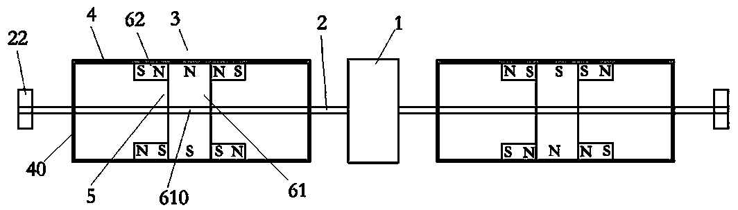
[0020] Example 1, such as figure 1 As shown, a two-way rotating magnetic field generating device includes a motor 1 and a motor shaft 2 installed on the motor 1, and a magnetic device 3 is installed on the motor shaft 2, and the magnetic device 3 includes an axial connection with the motor shaft 2. A sleeve 4 extending in the same axial direction and installed on the motor shaft 2 and a magnetic assembly 5 arranged in the sleeve 4 . The sleeve 4 is preferably a metal sleeve made of metal, for example, a stainless steel cylinder with a cavity inside. The sleeve 4 is a sealed cylindrical tube with a cover 40 fixed at both ends of the sleeve in the axial direction, and its central axis is on the same line as the central axis of the motor shaft 2 . The motor shaft 2 can also be equipped with a bearing 22, which is beneficial to assembly, improves stability, fluency, and the like. The motor 1 is a biaxial motor with motor shafts 2 on its opposite sides and a magnetic device 3 is ...

Embodiment 2

[0023] Example 2, such as figure 2 As shown, the difference between it and Embodiment 1 lies in the difference of the magnetic assembly 5. In this embodiment, the magnetic assembly 5 includes two sets of magnetic units perpendicular to the axial direction of the sleeve 4, and the magnetic units include A longitudinally spaced magnetic block 71 arranged axially on the barrel 4 and one end of which fits against the inner wall of the sleeve 4 and a longitudinally spaced magnetic block 71 located near one end of the longitudinally spaced magnetic block 71 fitted to the inner wall of the sleeve 4 On both sides of the sleeve 4 in the axial direction, there are horizontally extending magnetic blocks 62 that are attached and fixed to the longitudinally spaced magnetic blocks 71 and extend along the axial direction. The longitudinally spaced magnetic blocks of the two magnetic units of the same magnetic assembly 5 The distance between the blocks 71 is perpendicular to the axial directio...

Embodiment 3

[0024] Embodiment 3 differs from Embodiment 1 in that: two or more magnetic devices 3 arranged at intervals are installed on the motor shaft 2 , that is, multiple magnetic devices 3 are arranged on the same motor shaft 2 .


PUM

PropertyMeasurementUnit
surface magnetismaaaaaaaaaa

Abstract

The invention relates to the technical field of magnetic health products, in particular to a two-way rotating magnetic field generator. The two-way rotating magnetic field generator comprises a motor and a motor shaft, wherein the motor shaft is arranged on the motor; a magnetic device is arranged on the motor shaft and comprises a sleeve and a magnetic assembly; the axial direction of the sleeve is consistent with the axial extension direction of the motor shaft; the sleeve is arranged on the motor shaft; and the magnetic assembly is arranged in the sleeve. The two-way rotating magnetic field generator has the advantages of high magnetic field, high stability, good heat dissipation and good magnetic health effect.

Description

technical field [0001] The invention relates to the technical field of magnetic health products, in particular to a bidirectional rotating magnetic field generating device. Background technique [0002] In the existing furniture, bedding and other fields, such as beds, chairs, sofas, etc., as well as some daily massage equipment, magnetic health care devices are used. Nowadays, moving magnetic products are gradually increasing. Among them, such as gyromagnetic The application of these products has attracted people's attention. However, many existing gyromagnetic devices have complex structures, poor assembly, and deviations in stability. Relatively speaking, the size of the magnetic field is not high, and the spatial distribution of the magnetic field is not optimized. The effective utilization rate of the magnetic field is not high, the magnetic health care effect is not good, the heat dissipation of the device is not high, the vibration is large, the noise is also large, a...

Claims


Application Information

Patent Timeline
Patent Type & Authority Patents(China)
IPC IPC(8): H02K7/14H01F7/02
CPCH01F7/0273H02K7/14
Inventor 李俊胡立江方志财
Owner HEYE HEALTH TECH CO LTD
Why Eureka
Try Eureka