
Tethered cables for contactless power and data transmission

A technology for data transmission and mooring cables, applied in the direction of insulated cables, parts of transformers/inductors, cables, etc., can solve the problems of high energy consumption, low wire strength, and high cost, and achieve improved coupling efficiency and good mechanical properties , Strong corrosion resistance

Active Publication Date: 2018-01-16
TIANJIN UNIV
View PDF4 Cites 0 Cited by
  • Summary
  • Abstract
  • Description
  • Claims
  • Application Information

AI Technical Summary

Problems solved by technology

The observation system using self-contained power supply needs to salvage the underwater sensor system regularly and replace the battery for the underwater sensor system, which is a huge project.
The wire transmission method has the disadvantages that the line joint is easy to corrode, the impact of sea water will cause the joint to loosen or detach, the wire strength is low, and it will break under the long-term action of sea water.
The data transmission methods between the underwater sensor of the observation system and the observation platform include wire transmission, sonar transmission, and non-contact transmission methods based on the principle of electromagnetic coupling. Restricted by large capacity, high cost, and limited communication distance
[0004] So far, the underwater sensors of the ocean observation system basically use self-capacity power supply. The non-contact power and data transmission based on the principle of electromagnetic coupling is a new transmission method with considerable advantages. There are few mature technologies in the world. According to reports, domestic research in this area has just started

Method used


Image

  • Tethered cables for contactless power and data transmission
  • Tethered cables for contactless power and data transmission
  • Tethered cables for contactless power and data transmission

Examples


Embodiment Construction

[0023] The present invention will be further described below in conjunction with the accompanying drawings.

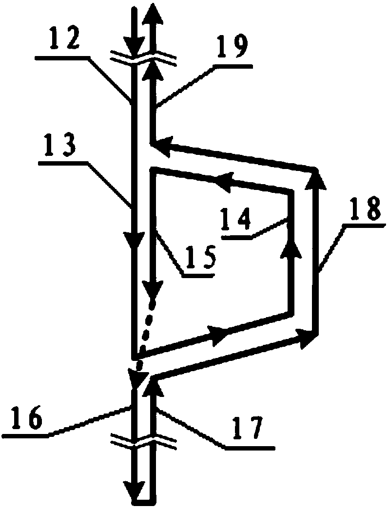
[0024] Such as figure 1 As shown, the mooring cable suitable for non-contact power and data transmission of the present invention includes an upper mooring cable body 4 and a lower mooring cable body 5, and the upper mooring cable body 4 and the lower mooring cable body 5 are both Consisting of a multi-core waterproof cable, the inner core of the waterproof cable is divided into two strands, and the upper mooring cable body 4 and the lower mooring cable body 5 are used not only as signal cables for power and data transmission, but also as ocean observation cables. System of mooring lines.

[0025] The upper end of the upper mooring cable body 4 is sequentially connected with an upper watertight load bearing 3 , a transmission cable 2 and a watertight joint 1 . The upper watertight load bearing 3 can be made of 316 stainless steel, and is used for fixed connection wit...


PUM


Abstract

The invention discloses a novel mooring cable suitable for non-contact power and data transmission. The novel mooring cable comprises an upper mooring cable body and a lower mooring cable body, wherein the upper end of the upper mooring cable body is sequentially connected with an upper watertight load-bearing device, a transmission cable and a watertight joint from bottom to top; the lower end of the lower mooring cable body is connected with a lower water-right load-bearing device; a trapezoidal branch structure is arranged between the upper mooring cable body and the lower mooring cable body and comprises an upper vulcanization branch node, an inner magnetic core cable and a lower vulcanization branch node, which are sequentially connected with one another from top to bottom; and an outer magnetic core cable is arranged between a side branch of the upper vulcanization branch node and the side branch of the lower vulcanization branch node. The novel mooring cable can ensure the stability of power transmission in an underwater environment through reducing the change of an inductance; and meanwhile, the cable is prevented from being wound due to the factors of flow and the like by a single cable structure.

Description

technical field [0001] The present invention relates to a mooring cable, more particularly, relates to a mooring cable suitable for non-contact power and data transmission. Background technique [0002] The offshore ocean observation system is a long-term, all-weather, fully automatic series of large-scale automated ocean instruments and equipment, mainly composed of various buoys, submarine buoys, survey sections, offshore platforms, volunteer ships and satellites, etc. Stable operation at sea. The sensing systems used by various observation equipment to monitor ocean information are divided into two parts, one is the above-water sensor system, and the other is the underwater sensor system. [0003] At present, there are two methods of power supply for underwater sensors in marine observation systems: the first is self-capacitance power supply, that is, the battery carried by the underwater sensor itself supplies power for itself; the second is contact wire power supply, t...

Claims


Application Information

Patent Timeline
Patent Type & Authority Patents(China)
IPC IPC(8): H01F38/14H01F27/28H01F27/29H01B7/28H01B7/282H01B7/18H01B7/02
CPCH01B7/02H01B7/18H01B7/2806H01B7/282H01F27/2828H01F27/29H01F38/14H01F2038/143
Inventor 李醒飞房诚谢子铭徐佳毅肖霖玲
Owner TIANJIN UNIV
Learn More