
Microdisplay dynamic target simulation module

A technology of microdisplay and dynamic target, which is applied in the direction of instrument, optics, cooling/ventilation/heating transformation, etc., can solve the problem of only static display and cannot simulate the target dynamically, and achieves the effect of widening the operating temperature.

Inactive Publication Date: 2016-05-04
XIAN MICROMACH TECH CO LTD
View PDF8 Cites 2 Cited by
  • Summary
  • Abstract
  • Description
  • Claims
  • Application Information

AI Technical Summary

Problems solved by technology

The disadvantage of this technique is that it cannot simulate the target dynamically, it can only be displayed statically, so there are obvious limitations

Method used


Image

  • Microdisplay dynamic target simulation module
  • Microdisplay dynamic target simulation module

Examples


Embodiment Construction

[0021] In order to facilitate the understanding of the present invention, the present invention will be described more fully below with reference to the associated drawings. Preferred embodiments of the invention are shown in the accompanying drawings. The above are only preferred embodiments of the present invention, and are not intended to limit the patent scope of the present invention. Any equivalent structure or equivalent process conversion made by using the description of the present invention and the contents of the accompanying drawings, or directly or indirectly used in other related technical fields , are all included in the scope of patent protection of the present invention in the same way.

[0022] Unless otherwise defined, all technical and scientific terms used herein have the same meaning as commonly understood by one of ordinary skill in the technical field of the invention. The terminology used herein in the description of the present invention is only for ...


PUM


Abstract

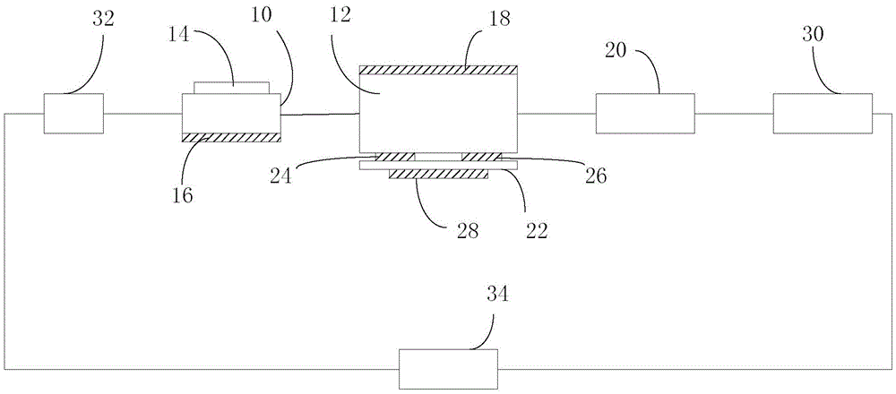
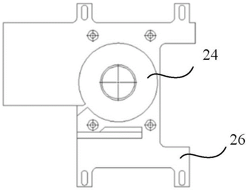
The invention provides a microdisplay dynamic target simulation module which comprises a microdisplay, a microdisplay circuit driving board, heaters and a temperature controller. The microdisplay is connected with the microdisplay circuit driving board, the heaters are arranged on the back face of the microdisplay and the front face and the back face of the microdisplay circuit driving board respectively, and the temperature controller is connected between the heaters arranged on the front face and the back face of the microdisplay; the temperature controller detects the real-time temperature of the microdisplay, when the temperature is lower than first preset temperature, the temperature controller is switched on, and the heaters start to heat; when the temperature is higher than second preset temperature, the temperature controller is switched off, and the heaters stop heating. By means of the microdisplay dynamic target simulation module, the usage temperature of the microdisplay can be effectively widened, and the microdisplay can normally work in a low-temperature environment to dynamically simulate a target.

Description

technical field [0001] The invention relates to the technical field of microdisplays, in particular to a dynamic target simulation module of a microdisplay, which is especially widely used in dynamic star simulators. Background technique [0002] At present, related products that use LCOS as a display device, such as spatial light modulators, are basically used at room temperature, and the operating temperature range specified by LCOS chip manufacturers is usually 0°C to 70°C, so in low temperature environments, such as- In an environment of 40° C. to 0° C., it is generally difficult to ensure normal operation, which makes the LCOS chip itself have defects in a low temperature environment. [0003] In the prior art, when the imaging device used as the target simulation module cannot meet the use requirements of -40°C to 70°C, a static differentiation plate is generally used as the imaging device, which is mainly coated on K9 glass. A layer of opaque metal film is formed, an...

Claims


Application Information

Patent Timeline
Patent Type & Authority Applications(China)
IPC IPC(8): G02F1/1333G02F1/1335G09F9/00H05K7/20
CPCG02F1/133382G02F1/133528G09F9/00H05K7/20954
Inventor 胡加杰王华杨小君
Owner XIAN MICROMACH TECH CO LTD
Learn More