Method for the ablation cutting of a workpiece by means of a pulsed laser beam

A pulsed laser and ray technology, used in laser welding equipment, glass cutting devices, welding/welding/cutting items, etc., can solve problems such as appearance defects and adverse effects on workpiece stability, and achieve the effect of less material removal

Active Publication Date: 2016-04-27
TRUMPF LASERSYST FOR SEMICON MFG
View PDF9 Cites 2 Cited by
  • Summary
  • Abstract
  • Description
  • Claims
  • Application Information

AI Technical Summary

Problems solved by technology

[0003] The above-mentioned sub-processing area not only forms appearance defects on the processed workpiece, but also adversely affects the stability of the workpiece

Method used


Image

  • Method for the ablation cutting of a workpiece by means of a pulsed laser beam
  • Method for the ablation cutting of a workpiece by means of a pulsed laser beam
  • Method for the ablation cutting of a workpiece by means of a pulsed laser beam

Examples


Embodiment Construction

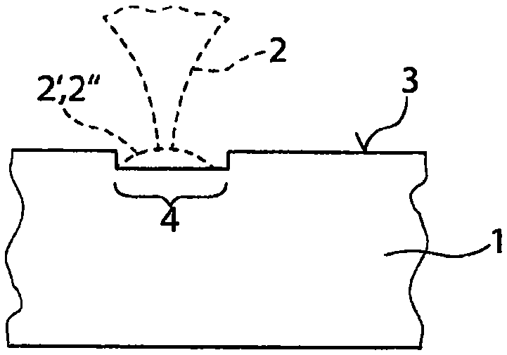
[0031] exist Figures 1a to 1d The individual method steps for performing the material-removing cutting according to the invention of a translucent workpiece 1 by means of a pulsed laser beam 2 are shown in an illustrative manner.

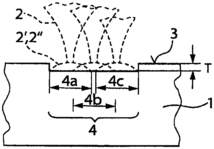
[0032] exist Figure 1a In the first method step shown in , the surface trajectory 4 ( Figure 2a ) through the workpiece surface (the upper side of the workpiece) 3, as the real material removal, the workpiece surface is pretreated. The transmissivity of the workpiece region in the vicinity of the surface is reduced by this pretreatment, for example by roughening the workpiece surface 3 with the aid of the laser beam 2 . Such as Figure 2a As shown, in the first method step, successive laser pulses 2 ′, 2 ″ of the pulsed laser beam 2 have a first pulse overlap 6 of, for example, 95% in the track direction 5 on the workpiece surface 3 1, so that successive pulses 2', 2" largely overlap each other.

[0033] In order to widen the preprocessed su...


PUM


Abstract

The method according to the invention for ablating an in particular transparent workpiece (1) by means of a pulsed laser beam (2) comprises the following steps: a) pretreating the workpiece surface (3) by moving the pulsed laser beam (2) over the workpiece surface (3) along a surface path (4), wherein consecutive laser pulses (2', 2") of the pulsed laser beam (2) have a first pulse overlap (61) on the workpiece surface (3a) in the path direction (5); and b) ablating the pretreated workpiece surface (3) by moving the pulsed laser beam (2) over the workpiece surface (3) along the surface path (4) multiple times, wherein consecutive laser pulses (2', 2") of the pulsed laser beam (2) have a second pulse overlap (62) on the workpiece surface (3) in the path direction (5), which second pulse overlap is less than the first pulse overlap (61).

Description

technical field [0001] The invention relates to a method for stripping or stripping cutting, in particular translucent, workpieces by means of pulsed laser radiation. In such a material-removing cutting method, workpiece material is successively removed from the workpiece by means of a laser beam. Background technique [0002] When cutting workpieces with the aid of a laser, in particular thin substrates such as glass, sapphire or similar materials, it is known that damage occurs not only in the region of the direct material removal on the upper side of the workpiece facing the laser beam , and usually also at a distance therefrom in the interior of the workpiece material or on the underside of the workpiece to form so-called secondary processing zones, in which the workpiece material is damaged by the laser process (local modification, for example melting ). Furthermore, the cause of the formation of the secondary processing zone is presumably undesired optical effects du...

Claims


Application Information

Patent Timeline
Patent Type & Authority Applications(China)
IPC IPC(8): B23K26/06B23K26/36B23K26/402B23K26/08B23K26/38C03B33/02
CPCB23K26/0869B23K26/38C03B33/0222B23K26/364B23K26/40B23K2103/50B23K26/3584B23K2103/54B23K26/0622B23K26/352B23K26/402
Inventor S·鲁斯D·阿尔德林克
Owner TRUMPF LASERSYST FOR SEMICON MFG
Why Eureka
Try Eureka