Method for manufacturing anisotropic dye film, anisotropic dye film manufactured by said manufacturing method, optical element including said anisotropic dye film, and liquid crystal element including said optical element
An anisotropy and manufacturing method technology, applied in the direction of optical elements, optics, polarizing elements, etc., can solve the problem of high cost, achieve excellent polarization performance, and suppress the effect of uneven film thickness or coating stripes
- Summary
- Abstract
- Description
- Claims
- Application Information
AI Technical Summary
Problems solved by technology
Method used
Image
Examples
preparation example Construction
[0215]
[0216]
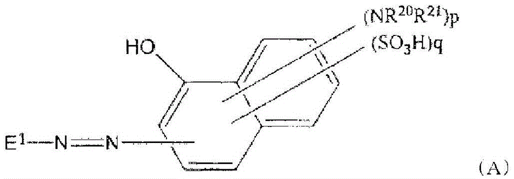
[0217] In 81 parts of water, add 18 parts of the azo compound represented by the formula (I) and 1 part of the compound represented by the formula (II), stir and dissolve, filter, remove the insoluble components, and obtain the combination for forming an anisotropic pigment film Object 1. The viscosity of the composition 1 for anisotropic dye film formation was 16.0 cP.
[0218] 【Chemical 3】
[0219]
[0220] 【Chemical 4】
[0221]
[0222]
[0223] In 79 parts of water, add 20 parts of the azo compound represented by the formula (I) and 1 part of the compound represented by the formula (II), stir and dissolve, filter, remove the insoluble components, and obtain the combination for forming an anisotropic pigment film Object 2. The viscosity of the composition 2 for anisotropic dye film formation was 40.0 cP.
[0224]
[0225] In 74 parts of water, add 25 parts of azo compounds represented by formula (I) and 1 part of compounds represented by ...
Embodiment 1
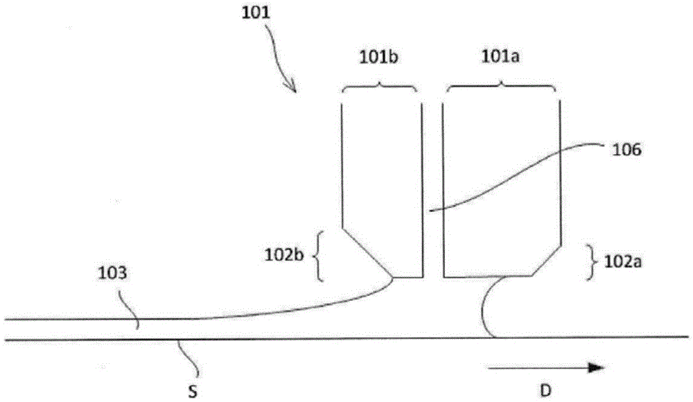
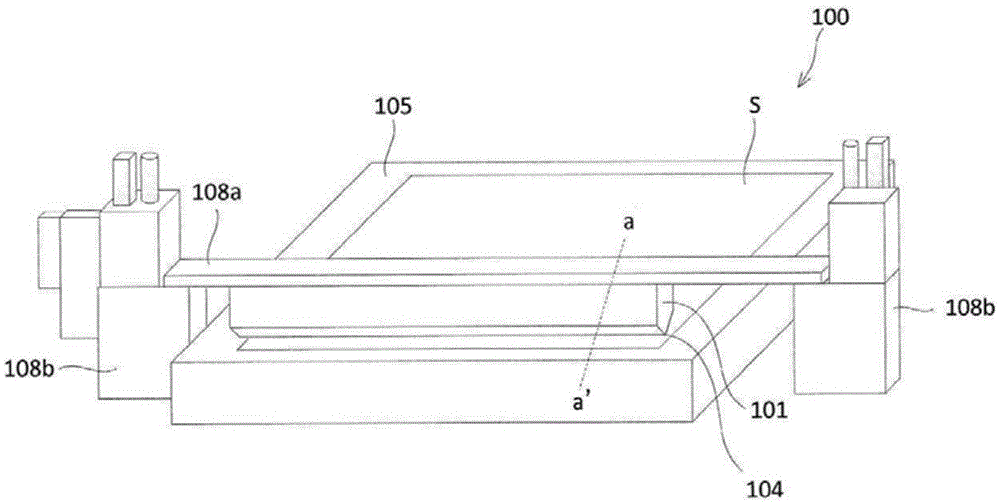
[0229] The length A of the part parallel to the coating surface of the anisotropic pigment film in the front die lip is 0.5 mm, and the length B of the part parallel to the coating surface of the anisotropic pigment film in the rear die lip is 0.1 mm. A die head with a slit width of 50 μm was used to apply the anisotropic pigment film-forming composition 1 on the above-mentioned coated substrate so that the rubbing direction of the substrate was parallel to the coating direction, and the film thickness during coating was is 3 μm.
[0230] The upper limit of the coating speed for coating without defects on the entire substrate was found, and it was found that coating was possible at 15 mm / s, and an anisotropic dye film 1 with a film thickness of about 0.3 μm was obtained.
[0231] In addition, preparation was performed on coating conditions of 24-26 degreeC and 40%RH-60%RH. The obtained anisotropic dye film 1 does not generate uneven film thickness or coating streaks, and the ...
Embodiment 2~6
[0233] Anisotropic dye film 2 was obtained as in Example 1, except that the lengths of A and B, the film thickness at the time of coating, and the composition for forming an anisotropic dye film used were changed to the values shown in Table 1. ~6.
[0234] Coating speed of the composition for anisotropic pigment film formation, film thickness of the obtained anisotropic pigment film, presence or absence of uneven film thickness and coating streaks, transmittance of the anisotropic pigment film, dichromatic Table 1 shows the measurement results of the ratio and degree of polarization.
PUM
| Property | Measurement | Unit |
|---|---|---|
| length | aaaaa | aaaaa |
| length | aaaaa | aaaaa |
Abstract
Description
Claims
Application Information
 - R&D
- Intellectual Property
- Life Sciences
- Materials
- Tech Scout
- Unparalleled Data Quality
- Higher Quality Content
- 60% Fewer Hallucinations
Browse by: Latest US Patents, China's latest patents, Technical Efficacy Thesaurus, Application Domain, Technology Topic, Popular Technical Reports.
© 2025 PatSnap. All rights reserved.Legal|Privacy policy|Modern Slavery Act Transparency Statement|Sitemap|About US| Contact US: help@patsnap.com


