Optical gas sensing device and sensing system thereof

A sensing device, optical technology, applied in measuring devices, material analysis through optical means, electrical components, etc., can solve the problems of the overall responsivity decrease and thermal conductivity increase of the micro-thermal radiation sensor, and achieve high absorption rate , reduce energy loss, improve the effect of responsiveness

Inactive Publication Date: 2017-07-11
张议聪
View PDF6 Cites 0 Cited by
  • Summary
  • Abstract
  • Description
  • Claims
  • Application Information

AI Technical Summary

Problems solved by technology

[0004] However, the upper and lower electrodes of the known surface micromachining technology are all arranged on the same side or the same surface of the substrate, so that when a voltage is applied to the upper and lower electrodes, the upper sensor is easy to absorb or contact the lower electrode of the lower layer, so that the thermal conductivity value increase, which in turn reduces the overall responsivity of the microthermal radiation sensor (Responsivity)

Method used


Image

  • Optical gas sensing device and sensing system thereof
  • Optical gas sensing device and sensing system thereof
  • Optical gas sensing device and sensing system thereof

Examples


Embodiment Construction

[0023] The preferred embodiments of the optical gas sensing device and its sensing system according to the present invention will be described below with reference to the relevant drawings. For ease of understanding, the same components in the following embodiments are described with the same symbols.

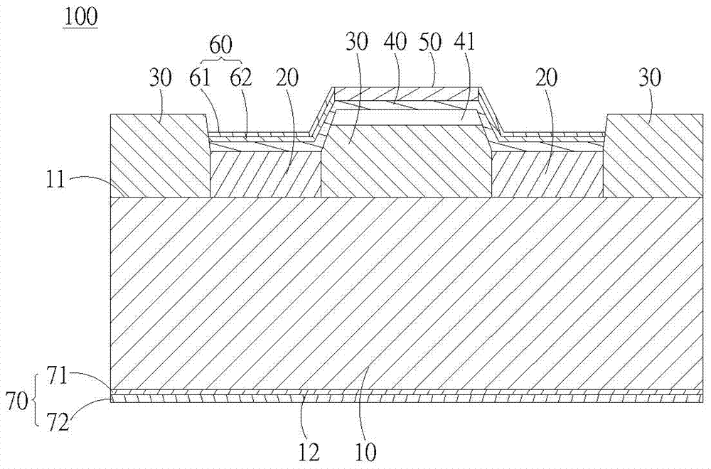
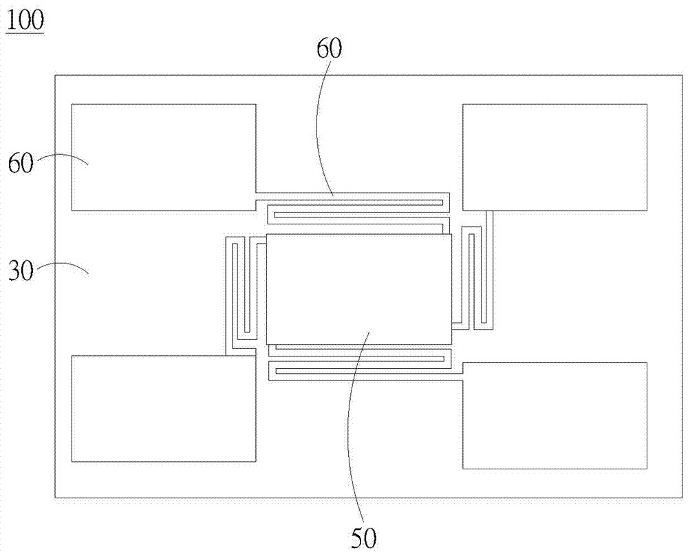
[0024] see Figure 1-3 , figure 1 It is a three-dimensional schematic diagram of a preferred embodiment of the optical gas sensing device of the present invention. figure 2 for figure 1 The optical gas sensing device is a side view of the substrate 10, the second electrode layer 70 and the reflective layer 30 cut along the section line A-A'. image 3 for figure 1 The top view of the optical gas sensing device.

[0025] The optical gas sensing device 100 of the present invention at least includes a substrate 10 , a plurality of electrode pads 20 , a reflective layer 30 , a sensing layer 40 , an absorbing layer 50 , a first electrode layer 60 and a second electrode layer 70 ...


PUM

PropertyMeasurementUnit
thicknessaaaaaaaaaa
thicknessaaaaaaaaaa
thicknessaaaaaaaaaa

Abstract

The invention discloses an optical gas sensor. The optical gas sensor comprises a substrate with a first surface and a second surface, a reflection layer arranged on the first surface of the substrate, plural electrode pads which are arranged on the first surface of the substrate and adjacent to the reflection layer, a sensing layer connected to the substrate via the electrode pads, an absorption layer arranged on the sensing layer, a first electrode layer which is arranged on the sensing layer and adjacent to the absorption layer and a second electrode layer arranged on the second surface of the substrate.

Description

technical field [0001] The present invention relates to an optical gas sensing device and its sensing system, in particular to an infrared gas sensing device and its sensing system. Background technique [0002] Known non-dispersive infrared (Non-dispersive Infrared, NDIR) technology is generally regarded as one of the best methods to measure the concentration of gas, which according to Beer's Law (Beer's Law) using the characteristics of gas in the infrared absorption band to measure the infrared through the Measure the intensity change before and after the gas, and then obtain the concentration of the gas to be measured by the intensity change of infrared rays. [0003] Generally speaking, the infrared sensor used in the non-dispersive infrared technology is a thermal infrared sensor (such as a Microbolometer). When the micro-thermal radiation sensor absorbs the infrared radiant energy, the temperature of the micro-thermal radiation sensor will change and its resistance v...

Claims


Application Information

Patent Timeline
Patent Type & Authority Patents(China)
IPC IPC(8): H01L31/09G01N21/3504
Inventor 张议聪魏章哲李岳轩
Owner 张议聪
Why Eureka
Try Eureka