
Mass concrete microscopic fracture testing system

A large-volume concrete, cracking test technology, applied in the direction of material analysis, measuring devices, instruments, etc., using acoustic wave emission technology, can solve the problem of inability to simulate the degree of constraint and temperature development process, unsuitable for large-volume concrete crack resistance, test methods Unable to respond to problems such as microscopic cracks

Active Publication Date: 2016-04-27
CHINA INST OF WATER RESOURCES & HYDROPOWER RES
View PDF8 Cites 7 Cited by
  • Summary
  • Abstract
  • Description
  • Claims
  • Application Information

AI Technical Summary

Problems solved by technology

[0003] The problems of the ring method are: the discreteness of the experimental data obtained is relatively serious, and it is limited to the strain value, and the mechanical properties cannot be quantitatively analyzed; the temperature and the restraint process are single and uncontrollable, and the degree of restraint and the temperature development process in the actual project cannot be simulated. ;Concrete with large aggregates cannot be tested due to size constraints
[0004] The problem with the plate method is that it cannot quantitatively measure the performance parameters of concrete, cannot evaluate the stress of concrete caused by temperature changes, and is not suitable for evaluating the crack resistance of mass concrete.
[0005] The axial restraint test method is to use the temperature stress testing machine to test the early cracking performance of concrete. The existing temperature stress testing machine takes the appearance of concrete macroscopic cracks as the test result during the test process. Generally, the expansion of concrete cracks starts from the microscopic cracks. At the beginning, and then expanded into macroscopic cracks, conventional test methods cannot reflect microscopic cracks

Method used


Image

  • Mass concrete microscopic fracture testing system
  • Mass concrete microscopic fracture testing system

Examples


Embodiment Construction

[0020] The present invention will be described in further detail below in conjunction with the accompanying drawings and embodiments.

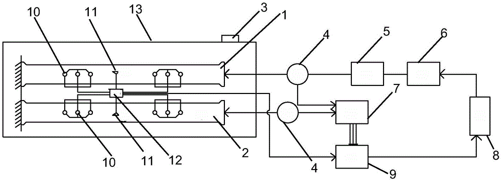
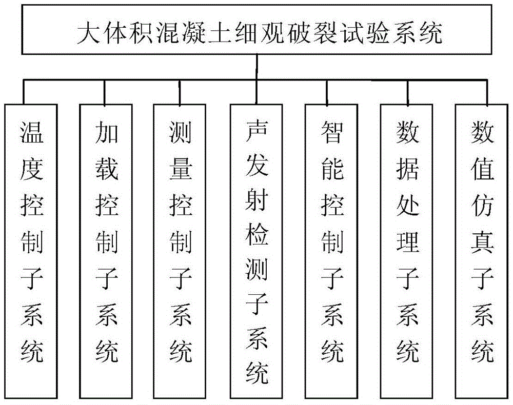
[0021] figure 1 It is a system composition block diagram of the present invention. As shown in the figure, the large-volume concrete mesoscopic cracking test system disclosed by the present invention includes a temperature stress testing machine and an acoustic emission detection device,

[0022] The temperature stress testing machine comprises a casing 13 for accommodating concrete specimens (constrained specimen 1 and free specimen 2), a heating and cooling system 3 on the chassis, a displacement sensor 4, a load cell 5, a stepper motor 6, The controller 8 used to control the action of the stepper motor, the signal amplifier 7 and the server 9 used to amplify the collected signal; the constrained specimen (shrinking under restrained conditions) and the free specimen ( Free contraction) is placed in the chassis, one end of the constrained s...


PUM


Abstract

The invention discloses a mass concrete microscopic fracture testing system. The mass concrete microscopic fracture testing system comprises a temperature stress testing machine and a sound emission detection device, wherein the temperature stress testing machine comprises a machine case for accommodating a concrete sample, a heating and cooling system, a displacement sensor, a force sensor, a stepper motor, a controller, a signal amplifier, a temperature sensor which is buried in the concrete sample, and a server, wherein the server is used for controlling the actions of the stepper motor according to data collected by each sensor and processing the data collected by each sensor to obtain temperature stress test parameters; the sound emission detection device comprises a sound emission sensor buried in the concrete sample and a signal processing unit, and the sound emission sensor is connected with the data input end of the server through the signal processing unit; concrete deformation data collected by the sound emission sensor are transmitted to the server after the amplification of the signal processing unit and analog-digital conversion processing. The system takes the occurrence of concrete microscopic fractures as a test result, so that accurate measurement of temperature parameters under concrete microscopic fractures can be realized.

Description

technical field [0001] The invention relates to a large-volume concrete mesoscopic cracking test system, which belongs to the technical field of water conservancy and hydropower engineering. Background technique [0002] Concrete cracks are the physical structural changes of concrete structures due to the effects of internal and external factors. The research on concrete cracks has important practical significance for technical fields such as water conservancy and hydropower engineering, civil engineering and construction engineering. At present, the main test method for studying concrete cracking is the restraint test method, which is mainly divided into the ring method, the flat plate method and the axial restraint test method. [0003] The problems of the ring method are: the discreteness of the experimental data obtained is relatively serious, and it is limited to the strain value, and the mechanical properties cannot be quantitatively analyzed; the temperature and the r...

Claims


Application Information

Patent Timeline
IPC IPC(8): G01N25/00G01N29/14
CPCG01N25/00G01N29/14
Inventor 张国新李松辉刘毅王振红
Owner CHINA INST OF WATER RESOURCES & HYDROPOWER RES
Learn More