
Package structure and method of fabricating the same

A technology of packaging structure and manufacturing method, applied in semiconductor/solid-state device manufacturing, electrical components, electrical solid-state devices, etc., can solve problems such as too long signal transmission path, increase manufacturing cost, and prone to warpage in the manufacturing process, and achieve shortened signal Effects of transmission path, reduction of signal loss, and improvement of electrical characteristics

Inactive Publication Date: 2016-04-20
PHOENIX & CORP
View PDF4 Cites 1 Cited by
  • Summary
  • Abstract
  • Description
  • Claims
  • Application Information

AI Technical Summary

Problems solved by technology

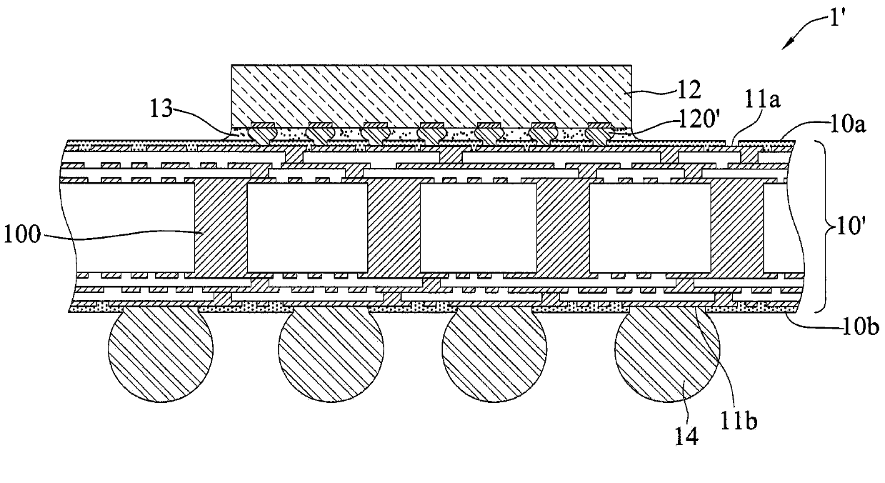
[0009] However, in the existing BGA package structure 1', the electrical performance cannot be improved due to the long signal transmission path (ie, the conductive element 14, the circuit layers 11a, 11b, and the conductive pillar 100) when used at a higher frequency or at a high speed. , so that the performance of the package structure 1' is limited
[0010] In addition, the existing BGA package structure 1' needs to make at least two layers of circuit layers 11a, 11b and conductive pillars 100 (such as drilling process, and copper is plated in the via holes as the connection between layers), Therefore, the overall structure is difficult to meet the thinning requirements, and it is difficult to reduce the manufacturing cost due to the complex and long production process
[0011] Moreover, the existing BGA package structure 1' needs to make more connection interfaces (such as between the conductive elements 14, the circuit layers 11a, 11b and the conductive pillars 100), and it is necessary to use a composite carrier board 10 with different materials for each layer. ', so a substantial increase in manufacturing cost
[0012] In addition, since the carrier board 10' is made of multiple layers (composed of various raw materials) materials whose thermal expansion coefficient (CTE) does not match the electrical properties, especially the CTE mismatch between the materials, it is easy to process during the manufacturing process. warped

Method used


Image

  • Package structure and method of fabricating the same
  • Package structure and method of fabricating the same
  • Package structure and method of fabricating the same

Examples


Embodiment Construction

[0044] The implementation of the present invention will be described below with reference to specific examples, and those skilled in the art can easily understand other advantages and effects of the present invention from the content disclosed in this specification.

[0045] It should be noted that the structures, proportions, sizes, etc. shown in the drawings attached to this specification are only used to match the content disclosed in the specification for the understanding and reading of those skilled in the art, and are not used to limit the implementation of the present invention. Limiting conditions, so there is no technical substantive meaning, any modification of structure, change of proportional relationship or adjustment of size, without affecting the effect and purpose of the present invention, should still fall within the scope of the present invention. The disclosed technical content must be within the scope covered. At the same time, terms such as "upper", "lowe...


PUM


Abstract

A package structure and a method for fabricating a package structure are provided. The method includes the steps of forming a wiring layer on a carrier by electroplating; disposing at least one electronic component on the wiring layer; forming on the carrier an insulating layer that encapsulates the wiring layer and the electronic component; and removing the carrier. With the single wiring layer having one surface electrically connected the at least one electronic component and the other surface electrically connected to a plurality of conductive elements, the package structure has a signal transmission path that is shortened.

Description

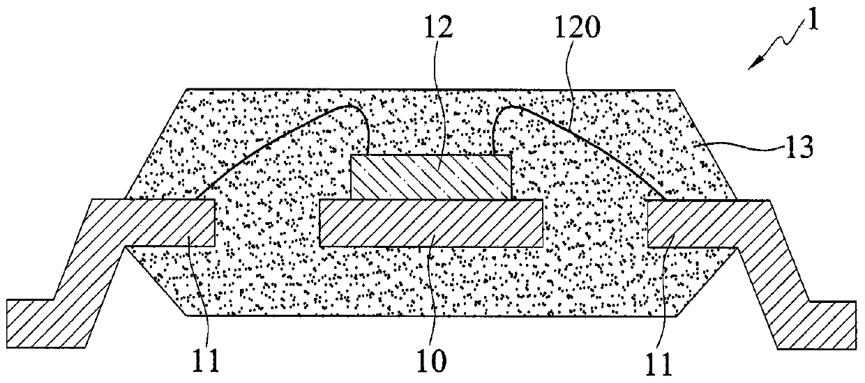
technical field [0001] The invention relates to a package structure, in particular to a package structure of a single-layer circuit layer and a manufacturing method thereof. Background technique [0002] With the development of semiconductor packaging technology, in smart phones, tablets, networks, notebook computers and other products, semiconductor devices have developed different packaging types, such as ball grid array (BGA), square Flat semiconductor package (Quad-FlatPackage, referred to as QFP) or quad flat non-lead type (QuadFlatNonleadPackage, referred to as QFN) semiconductor package, etc. [0003] Such as Figure 1A As shown, the existing QFP package structure 1 includes: a bearing base 10, a plurality of guide pins 11 located around the bearing base 10, bonded to the bearing base 10 and electrically connected to the guide pins 11 with a plurality of welding wires 120 The electronic component 12 and the insulating layer 13 such as encapsulant covering the electro...

Claims


Application Information

Patent Timeline
Patent Type & Authority Applications(China)
IPC IPC(8): H01L23/498H01L21/48H01L21/56H01L21/60
CPCH01L23/3107H01L21/2885H01L21/568H01L21/6835H01L21/768H01L23/16H01L23/49541H01L23/49589H01L24/16H01L24/48H01L24/81H01L24/85H01L25/16H01L2221/68359H01L2224/04105H01L2224/16245H01L2224/48245H01L2224/81005H01L2224/81193H01L2224/85005H01L2924/15311H01L2924/19041H01L2924/19042H01L2924/19043H01L2924/19105H01L2924/3511
Inventor 许诗滨刘智文吴唐仪胡书玮
Owner PHOENIX & CORP
Learn More