
Elastic-seal valve seat structure of fixed ball valve

An elastic sealing and fixing ball valve technology, applied in valve devices, cocks including cut-off devices, engine components, etc., can solve the problems of high manufacturing cost, long cycle, large manpower and material resources, achieve stable and efficient sealing, and improve the specific pressure of sealing. Effect

Inactive Publication Date: 2016-04-20
WUXI SMART AUTO CONTROL ENG CO LTD
View PDF5 Cites 5 Cited by
  • Summary
  • Abstract
  • Description
  • Claims
  • Application Information

AI Technical Summary

Problems solved by technology

[0003] In the design and production process of metal-sealed trunnion ball valves, different hardening treatments will be adopted for the sealing surface of the valve ball and seat according to different working conditions. Alloy, spray welding Ni60 nickel-based alloy, spray tungsten carbide, etc. After such hardening treatment on the sealing surface, the service life of the valve sealing pair can be greatly improved, but the process is complicated and the manufacturing cost is high.
Moreover, limited by the accuracy of processing equipment and the customer's requirements for leakage levels, metal-sealed trunnion ball valves usually require paired grinding of the sealing surfaces of the valve ball and valve seat, which requires a lot of manpower and material resources; once the valve reaches a certain service life , it is often necessary to replace the valve ball and the valve seat as a whole during inspection and maintenance, which consumes a lot of money and takes a long time

Method used


Image

  • Elastic-seal valve seat structure of fixed ball valve
  • Elastic-seal valve seat structure of fixed ball valve
  • Elastic-seal valve seat structure of fixed ball valve

Examples


Embodiment Construction

[0016] The present invention will be further described below in conjunction with specific examples.

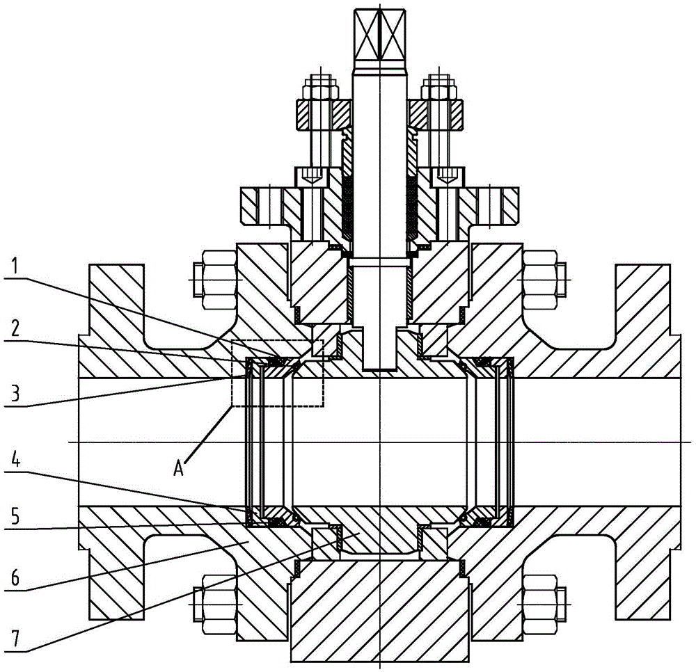
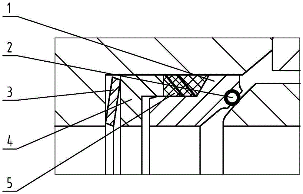
[0017] The elastic sealing valve seat structure of the fixed ball valve includes a valve seat 1, an O-ring 2, an elastic support body 3, a support ring 4, a packing 5, a valve body 6 and a valve ball 7; 6 is provided with an inner step, and the inner step is coaxial with the flow channel of the valve body 6. In the inner step, an elastic support body 3, a support ring 4, a packing 5 and a valve seat 1, and one end of the elastic support body 3 are arranged. It is against the bottom surface of the inner step, the other end of the elastic support body 3 is against the support ring 4, the other end of the support ring 4 is against the packing 5, the packing 5 is against the valve seat 1, and the valve seat 1 on the side facing the valve ball 7 A spherical groove is opened on the top, and the corresponding O-ring 2 is embedded in the spherical groove, and the O-ring 2 is in contac...


PUM


Abstract

The invention relates to an elastic-seal valve seat structure of a fixed ball valve. One side in the valve body adjacent to a valve ball is provided with an inner step; the inner step and the flow channel of the valve body are arranged coaxially; an elastic support body, a support ring, a filler and a valve seat are arranged in the inner step; one end of the elastic support body abuts against the bottom surface of the inner step, and the other end of the elastic support body abuts against the support ring; the other end of the support ring abuts against the filler; the filler abuts against the valve seat; one side of the valve seat towards the valve ball is provided with a spherical groove; an O ring is embedded in the spherical groove; and the O ring contacts the valve ball. Under the driving actions of the elastic compensation force provided by the elastic support body and the medium pressure, the O ring is forced to adhere to the valve ball to generate elastic deformation, thereby forming the reliable seal. Since one end of the filler adopts an inner conical surface structure, the elastic compensation force acted by the elastic support body on the support ring and the medium pressure can be laterally decomposed to enhance the seal specific pressure, so that the seal is stable and efficient.

Description

technical field [0001] The invention relates to a valve seat structure of a valve body, in particular to an elastic sealing valve seat structure of a fixed ball valve. Background technique [0002] The metal seal of the fixed ball valve is commonly known as the hard seal. One side of the sealing pair is a fixed ball made of metal material, and the other side is also a valve seat made of metal material. The elastic force provided by the small compression spring or disc spring arranged between the valve seat and the valve body is applied to the valve seat to realize the tight fit between the valve seat and the valve ball to achieve forced sealing. This kind of metal sealing structure has long service life, good temperature resistance, corrosion resistance and wear resistance, and superior mechanical properties. [0003] In the design and production process of metal-sealed trunnion ball valves, different hardening treatments will be adopted for the sealing surface of the valve...

Claims


Application Information

Patent Timeline
Patent Type & Authority Applications(China)
IPC IPC(8): F16K5/06F16K5/20
CPCF16K5/0663F16K5/20
Inventor 陈彦何甜庭史强修王文明
Owner WUXI SMART AUTO CONTROL ENG CO LTD
Learn More