Electromagnetic iron plate of electronic jacquard of narrow-width loom

An electronic jacquard and electromagnet plate technology, which is applied in the fields of jacquard machines, textiles, textiles and papermaking, etc., can solve the problem of errors in the bending angle of the sheet metal parts of the electromagnet head and the position of the inlaid nut, and the uneven position of the working end surface of the electromagnet Problems such as unevenness, stability, and poor consistency can be solved to achieve stable assembly effects, improve efficiency, and reduce the number of uses

Inactive Publication Date: 2016-04-13
JAKOB MULLER CHINA CO LTD
View PDF7 Cites 0 Cited by
  • Summary
  • Abstract
  • Description
  • Claims
  • Application Information

AI Technical Summary

Problems solved by technology

[0002] Generally, the connection position between the electromagnet and the copper strip is the bent sheet metal part and the inlaid nut. Because the bending angle of the electromagnet head sheet metal part and the position of the inlaid nut are relatively prone to errors, when the screw is locked, it is very easy to The phenomenon that the position of the working end face of the electromagnet is uneven after the assembly is completed
The electromagnet assembly position of the electromagnet is the sheet metal part and the inlaid nut. The stability and consistency are poor, and special pneumatic components are required to clamp the electromagnet, which is more labor-intensive.
[0003] The invention provides an electromagnet plate, which is used to solve the position consistency of the working end face of the electromagnet on the electromagnet plate, and avoid the needle skipping phenomenon of subsequent machines caused by the assembly of the electromagnet plate

Method used


Image

  • Electromagnetic iron plate of electronic jacquard of narrow-width loom
  • Electromagnetic iron plate of electronic jacquard of narrow-width loom
  • Electromagnetic iron plate of electronic jacquard of narrow-width loom

Examples


Embodiment Construction

[0021] The present invention will be described in detail below with reference to the accompanying drawings and in combination with embodiments.

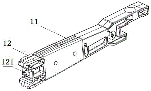
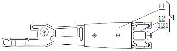
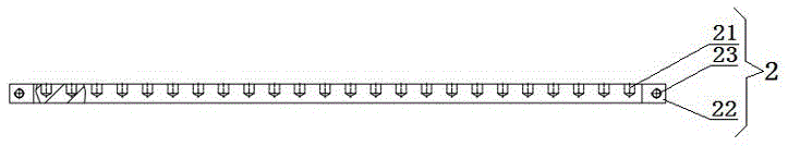
[0022] refer to Figure 1 to Figure 4 As shown, a narrow-width loom electronic jacquard faucet electromagnet board includes a PCB board 3, an electromagnet 1 and a copper strip 2 arranged on the PCB board 3, the electromagnet 1 includes an electromagnet body 11, and the electromagnet 1 includes an electromagnet body 11. One end of the electromagnet main body 11 is fixedly connected with a connecting piece 12, and the outer end surface of the connecting piece 12 is provided with a raised pin 121, and the copper bar 2 is provided with a limiting hole 21 that snaps and fits with the pin 121, In this embodiment, each copper strip 2 is provided with a row of equally spaced limiting holes 21 .

[0023] refer to Figure 5 and Image 6 As shown, the PCB board 3 is fixed on an aluminum base plate 4 by nuts and flat washers 8, the bottom of...


PUM


Abstract

The invention discloses an electromagnetic iron plate of an electronic jacquard of a narrow-width loom. The electromagnetic iron plate comprises a PCB (Printed Circuit Board), an electromagnet and a copper bar, wherein the electromagnet and the copper bar are arranged on the PCB; the electromagnet comprises an electromagnet main body; one end of the electromagnet main body is fixedly connected with a connecting piece; a raised pin post is arranged on the outer end surface of the connecting piece; a limiting hole which is matched with the pin post in a clamping way is formed in the copper bar. The electromagnetic iron plate disclosed by the invention has a more convenient assembling way and a stable assembling effect; meanwhile, the using amount of standard parts-screws is reduced, so that the efficiency is greatly increased, and the cost is reduced.

Description

technical field [0001] The invention belongs to the technical field of modernization of traditional narrow-width looms, and in particular relates to an electromagnet plate for electronic jacquard taps of narrow-width looms. Background technique [0002] Generally, the connection position between the electromagnet and the copper strip is the bent sheet metal part and the inlaid nut. Because the bending angle of the electromagnet head sheet metal part and the position of the inlaid nut are relatively prone to errors, when the screw is locked, it is very easy to After the assembly is completed, the position of the working end face of the electromagnet is uneven. The electromagnet assembly position of the electromagnet is the sheet metal part and the electromagnet plate with the nut embedded, the stability and consistency are poor, and it is necessary to use special pneumatic components to clamp the electromagnet, which is more labor-intensive. [0003] The invention provides a...

Claims


Application Information

Patent Timeline
Patent Type & Authority Applications(China)
IPC IPC(8): D03C3/20D03C3/26
CPCD03C3/20D03C3/26
Inventor 姚蕴霰李玲华
Owner JAKOB MULLER CHINA CO LTD
Why Eureka
Try Eureka