
Low-temperature plasma generator with hexagon pipe-type structure

A low-temperature plasma and generator technology, applied in the direction of plasma, electrical components, etc., can solve the problems of increasing the use of dielectric layer materials, large demand for plate raw materials, and the space utilization rate has not reached the highest level, so as to improve the space utilization rate. , the effect of saving usage

Inactive Publication Date: 2016-04-06
HUAZHONG UNIV OF SCI & TECH
View PDF9 Cites 5 Cited by
  • Summary
  • Abstract
  • Description
  • Claims
  • Application Information

AI Technical Summary

Problems solved by technology

[0003] In the two flat-plate electrode discharges and coaxial cylindrical electrode discharges that use dielectric barrier discharge to generate low-temperature plasma, at present, the amount of low-temperature plasma generation is mainly increased by changing the above factors, but because only a single device is considered in the experimental conditions In practice, in order to obtain a sufficient amount of high-density low-temperature plasma, multiple cylindrical generator tubes or flat-plate generator tubes are often connected in parallel in experiments, and the cylindrical generator tubes Because there is a gap between adjacent cylinders when the tubes are connected in parallel, the space utilization rate has not reached the highest within a limited space; and when the flat-plate generator is arranged in a matrix, each positive plate must need a negative plate. , In this way, in order to generate a sufficient amount of low-temperature plasma, the demand for plate raw materials is relatively large, and at the same time, the amount of dielectric layer materials used will also increase.

Method used


Image

  • Low-temperature plasma generator with hexagon pipe-type structure
  • Low-temperature plasma generator with hexagon pipe-type structure

Examples


Embodiment Construction

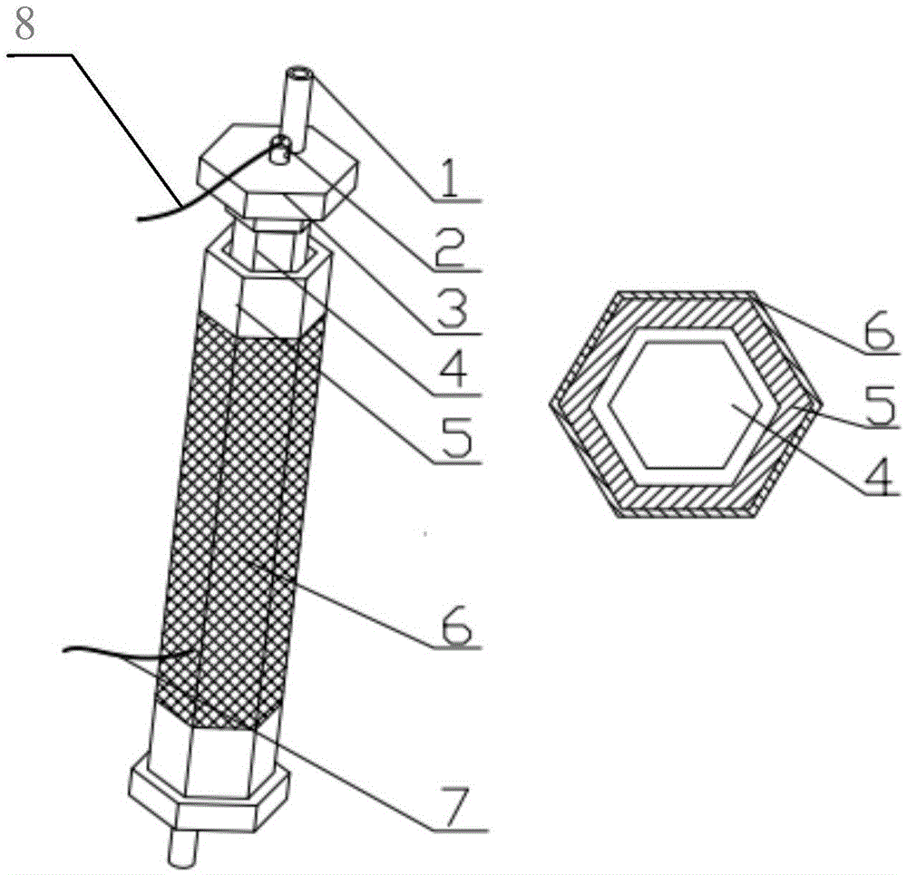
[0010] The present invention can be used to remove harmful inorganic (NO x , SO x ) and organic gases (VOCs). The invention proves through experiments that the single low-temperature plasma generator with hexagonal tubular structure can achieve above 99% removal rate of the above gases.

[0011] The present invention will be described in further detail below in conjunction with the accompanying drawings and embodiments. Advantageous features of the present invention will be apparent from the following description and claims. It should be noted that the drawings are all in a very simplified form and use very precise ratios, and are only used for the purpose of clearly and conveniently assisting in describing the embodiments of the present invention. In addition, the technical features involved in the various embodiments of the present invention described below can be combined with each other as long as they do not constitute a conflict with each other.

[0012] Such as fig...


PUM


Abstract

The present invention discloses a low-temperature plasma generator with a hexagon pipe-type structure. The low-temperature plasma generator comprises a copper rod, a generator cavity and a metallic mesh. The generator cavity is in the shape of a regular hexagon pipe, is made of quartz glass or corundum and is used as a medium in the middle of a discharging gap. The shape of the copper rod is the same with that of the generator cavity, and the copper rod is arranged in the generator cavity; both ends of the copper rod are sealed and fixed by positioning stoppers, and a through hole used for installing an aeration pipe is formed in each positioning stopper; and the metallic mesh wraps the outer surface of the generator cavity, and is used as a grounded negative electrode so as to ensure normal discharging, and fixes the generator cavity. During operation, the copper rod is connected to a high-voltage power source positive electrode by a positive electrode wiring head, the metallic mesh is connected to a high-voltage power source negative electrode by an external high-voltage wire, and after the generator is electrified, violet low-temperature plasma is generated in a slit between the copper rod and the generator cavity, and the generation amount of the low-temperature plasma is increased. When a plurality of low temperature plasma generators are connected in parallel, a space utilization rate can be improved, and the usage amount of medium materials and negative materials can be reduced.

Description

technical field [0001] The present invention relates to a low-temperature plasma generator, and more particularly, relates to a generator that utilizes a hexagonal tubular structure DBD (dielectric barrier discharge) to generate low-temperature plasma. Background technique [0002] At present, there are basically two ways for DBD equipment to generate low-temperature plasma, one of which is flat plate electrode discharge, and the other is coaxial cylindrical electrode discharge. Ye Zhenxin and others proposed a parallel plate electrode discharge device ("Analysis of factors related to dielectric barrier discharge power", Electromechanical Technology, 2011, 34(1): 41-43), which uses 4mm ordinary glass as the discharge medium, Adjust the discharge gaps to 2mm, 2.5mm and 3mm respectively, and keep other parameters constant, and draw the conclusion that the DBD discharge power decreases with the increase of the electrode gap; When it is close to the natural resonant frequency, ...

Claims


Application Information

Patent Timeline
IPC IPC(8): H05H1/24
CPCH05H1/2406
Inventor 袁旭东孙路石聂圻春潘悦左忠琪王晔袁旭君
Owner HUAZHONG UNIV OF SCI & TECH
Learn More