
Plasma vacuum pump

A vacuum pump and plasma technology, applied in ion diffusion discharge tubes, particle separation tubes, etc., can solve problems such as very high initial pressure requirements, resistance to atmospheric shock, damage to molecular pumps, etc., and achieve simple structure, low cost, and no vibration Effect

Inactive Publication Date: 2016-04-06
徐建宁
View PDF0 Cites 0 Cited by
  • Summary
  • Abstract
  • Description
  • Claims
  • Application Information

AI Technical Summary

Problems solved by technology

[0002] The current molecular pump relies on the high-speed rotation of the turbine group to increase the kinetic energy of the pumped gas, so as to achieve the purpose of degassing; because the turbine group is a rigid structure, the initial pressure of the pumped gas is very high: generally around 5Pa. Able to work, but not resistant to atmospheric shock; once the molecular pump is subjected to atmospheric shock, it is likely to be damaged, or even irreparable

Method used


Image

  • Plasma vacuum pump
  • Plasma vacuum pump

Examples


Embodiment Construction

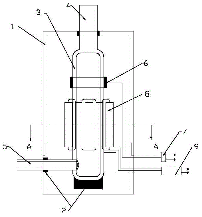
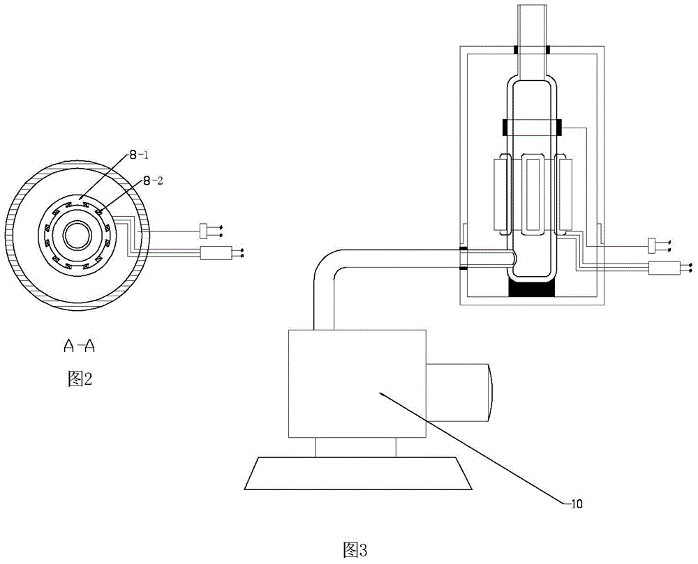
[0018] Such as figure 1 , 2 Shown: a plasma vacuum pump, including a casing 1, a glass pump body 3 set in the casing, an air intake pipe 4 and an exhaust pipe 5 connected to the glass pump body 3, and an electron emission ring 6 set on the glass pump body 3 And the rotating coil 8, the high-frequency generator 7 for the electron emission ring 6 power supply, the frequency converter 9 for the rotating coil 8 power supply; it is characterized in that: the described glass pump body 3 is that the quartz glass tube is made into a bottle shape, and the glass Both ends of the pump body 3 are welded with an intake pipe 4 and an exhaust pipe 5; the exhaust pipe 5 is welded in the radial direction of the glass pump body 3; the electron emission ring 6 is set on the front of the glass pump body 3; The rotating coil 8 is set in the middle and rear part of the glass pump body 3; the glass pump body 3 with the electron emission ring 6 and the rotating coil 8 is inserted into the shell 1; t...


PUM


Abstract

The invention discloses a plasma vacuum pump. An electron emission ring and a rotating coil sleeve the external wall of a glass pump body. Gas intake and exhaust pipes are welded at the two ends of the glass pump body. The gas intake pipe is used for being connected with a pumped container. The gas exhaust pipe is used for being connected with a previous vacuum pump. Gas entering the glass pump body is partially ionized by utilizing the electron emission ring to form plasma gas which rotates at high speed in a rotating magnetic field formed by the rotating coil. Plasma gas drives gas molecules which are not ionized to rotate at high speed due to the viscosity effect of gas so that an eddy generation center vacuum area is formed for degassing. No mechanical moving parts are arranged in high-speed rotation of plasma gas in the rotating magnetic field so that the plasma vacuum pump has no vibration and is simple in structure, low in energy consumption and atmospheric-impact-resistant.

Description

technical field [0001] The invention relates to a plasma vacuum pump, in particular to the field of high vacuum degassing. Background technique [0002] The current molecular pump relies on the high-speed rotation of the turbine group to increase the kinetic energy of the pumped gas, so as to achieve the purpose of degassing; because the turbine group is a rigid structure, the initial pressure of the pumped gas is very high: generally around 5Pa. It can work, and it is not resistant to atmospheric shock; if the molecular pump is damaged by atmospheric shock, it may even be irreparable. Contents of the invention [0003] The invention provides a plasma vacuum pump, which is that an electron emission ring and a rotating coil are set on the outer wall of a glass pump body, and inlet and exhaust pipes are welded at both ends of the glass pump body; the inlet pipe is used to connect with the pumped container, and the exhaust pipe is used It is connected with the front-stage va...

Claims


Application Information

Patent Timeline
IPC IPC(8): H01J41/12
Inventor 徐建宁
Owner 徐建宁
Learn More