
Double-magnetism barrier tunnel junction and self-rotating electronic device comprising the same

A technology of spintronics and tunnel junction, applied in the direction of magnetic field controlled resistors, components of electromagnetic equipment, etc., can solve the problems that hinder the practical application of double barrier magnetic tunnel junction

Active Publication Date: 2016-03-30
INST OF PHYSICS - CHINESE ACAD OF SCI
View PDF10 Cites 10 Cited by
  • Summary
  • Abstract
  • Description
  • Claims
  • Application Information

AI Technical Summary

Problems solved by technology

Although a significant quantum resonant tunneling effect can be observed in this structure, this structure has the same problem as the traditional double-barrier magnetic tunnel junction based on MgO barrier layer: due to the potential well between the two barrier layers The thickness of the middle magnetic layer is very thin, generally in the range of 0.5-5nm, so it is difficult to stop the etching process precisely at the middle magnetic layer to expose and lead out the middle magnetic layer
This problem also hinders the practical application of double-barrier magnetic tunnel junctions in various spintronic devices.

Method used


Image

  • Double-magnetism barrier tunnel junction and self-rotating electronic device comprising the same
  • Double-magnetism barrier tunnel junction and self-rotating electronic device comprising the same
  • Double-magnetism barrier tunnel junction and self-rotating electronic device comprising the same

Examples


Embodiment Construction

[0037] The subheadings are provided here for convenience of illustration only and are not intended to limit the scope of the present invention.

[0038] double magnetic barrier tunnel junction

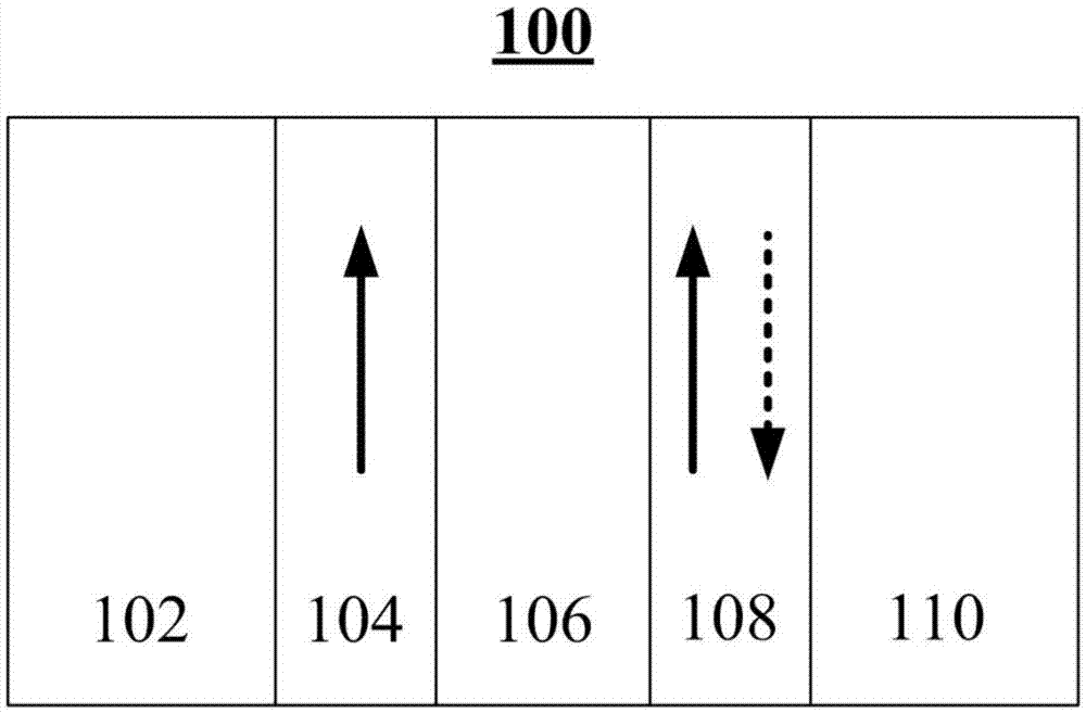
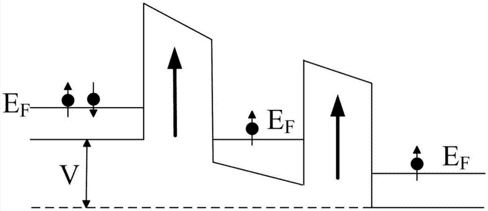
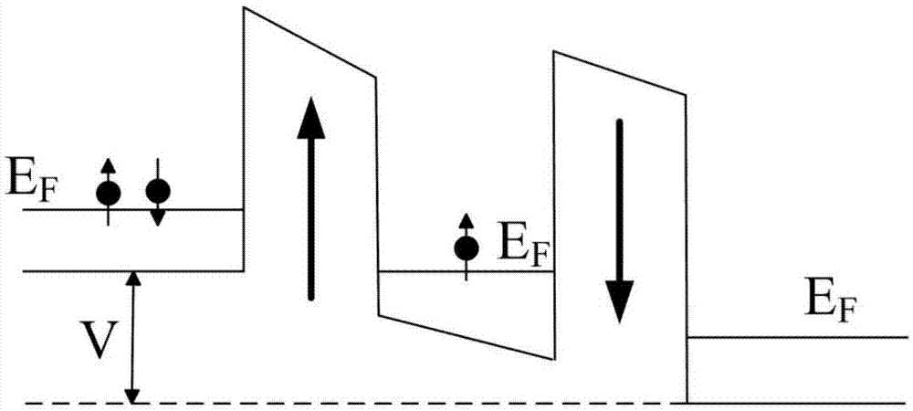
[0039] figure 1 A multilayer structure of a double magnetic barrier tunnel junction 100 according to an exemplary embodiment of the present invention is shown. Figure 2A and Figure 2B Schematically shows figure 1 The energy band diagram of the double magnetic barrier tunnel junction 100 is shown. It should be noted that in order to Figure 2A and Figure 2B The energy band diagram shown with figure 1 Corresponding to the multilayer structure shown, in order to facilitate the understanding of the shown energy band diagram, figure 1 The multiple layers included in the double magnetic barrier tunnel junction 100 are shown stacked laterally rather than one above the other.

[0040] refer to figure 1 , the double magnetic barrier tunnel junction 100 includes a first conductive ...


PUM

PropertyMeasurementUnit
Thicknessaaaaaaaaaa

Abstract

The invention discloses a double-magnetism barrier tunnel junction and a self-rotating electronic device comprising the same. The double-magnetism barrier tunnel junction comprises a first conductive layer, a first barrier layer arranged on the first conductive layer, and a second conductive layer arranged on the first barrier layer, a second barrier layer arranged on the second conductive layer, and a third conductive layer arranged on the second barrier layer, wherein each of the first barrier layer and the second barrier layer is made of the magnetic insulation material.

Description

technical field [0001] The present invention generally relates to the field of spin electronics, and more particularly, relates to a double magnetic barrier tunnel junction and a spin electronics device including the double magnetic barrier tunnel junction. Such a spin electronics device includes but Not limited to spin diodes, spin transistors, magnetosensitive sensors, magnetic memories, spin oscillators, temperature sensors, and spin logic devices, among others. Background technique [0002] Since the discovery of tunneling magnetoresistance (TMR) in Fe / Ge / Co multilayers in 1975 and giant magnetoresistance (GMR) in magnetic multilayers in 1988, physics and materials in spintronics Scientific research and applications have made great progress, especially the tunneling transport properties of spin-related electrons in magnetic tunnel junctions and the tunneling magnetoresistance effect have become one of the important research fields in condensed matter physics. In 1995, M...

Claims


Application Information

Patent Timeline
IPC IPC(8): H01L43/02H01L43/08
CPCH10N50/80H10N50/10
Inventor 韩秀峰孔文洁黄黎吴昊万蔡华
Owner INST OF PHYSICS - CHINESE ACAD OF SCI
Learn More