
Sample measuring cell

A technology for measuring cells and samples, applied in measuring devices, material analysis through optical means, instruments, etc., can solve problems such as inability to adapt to the measurement environment, limited compactness, and reduced reflectivity of high-reflection coatings, and achieve environmental adaptability Long optical path, strong environmental adaptability, and improved environmental adaptability

Inactive Publication Date: 2016-03-30
邓文平
View PDF9 Cites 11 Cited by
  • Summary
  • Abstract
  • Description
  • Claims
  • Application Information

AI Technical Summary

Problems solved by technology

Whether it is a metal reflective film or a dielectric reflective film, due to the limited adhesion between the film layers, the adhesion between the film layer and the substrate material, and the compactness of the film layer, when the high reflective film layer is placed at a high temperature , high humidity, high dust, corrosive and other harsh environments, the gas, water vapor and impurities in the environment are easy to enter between the layers of the high reflective film layer and the connection between the high reflective film layer and the glass substrate, making the high The reflective film layer is easily damaged; in addition, in the preparation process of the high reflective film layer, foreign particles are generally introduced, and the introduced particle foreign matter will cause defects in the high reflective film layer. When it is in the environment, the damage will be aggravated, which not only reduces the reflectivity of the high-reflection film layer and loses light energy, but also the film layer that falls off during the destruction process may block the light path, further reducing the collection efficiency of light energy, and even make the glass Deformation and rupture under the stress of the high-reflection film layer, resulting in poor environmental adaptability of the sample measurement cell based on the coating technology mirror, unable to adapt to different measurement environments, and cannot be used normally in harsh environments

Method used


Image

  • Sample measuring cell
  • Sample measuring cell
  • Sample measuring cell

Examples


Embodiment Construction

[0030] The present invention will be described in detail below in conjunction with specific embodiments shown in the accompanying drawings. However, these embodiments do not limit the present invention, and any structural, method, or functional changes made by those skilled in the art according to these embodiments are included in the protection scope of the present invention.

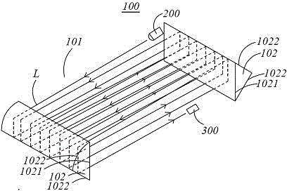
[0031] Such as figure 1 and figure 2 As shown, in one embodiment of the present invention, the sample measurement cell 100 includes a reflective cavity 101 and at least one reflective structure 102; the reflective cavity 101 is used to accommodate the sample to be measured, and the at least one reflective structure 102 is arranged The boundary of the reflective cavity 101; wherein, the reflective structure 102 includes at least one contact surface 1021 and two reflective surfaces 1022, the contact surface 1021 contacts the sample to be measured, and the reflective surface 1022 is away from the sample...


PUM


Abstract

The invention discloses a sample measuring cell. The sample measuring cell comprises a reflection cavity and at least a reflection structure, wherein the reflection cavity is used for containing samples to be measured; the reflection structures are arranged on the boundary of the reflection cavity and comprise at least a contact surface and two reflecting surfaces; the contact surfaces are used for coming into contact with the samples; the reflecting surfaces are far away from the samples; and the reflecting surfaces are fully reflecting surfaces or are not fully reflecting surfaces. The sample measuring cell has the beneficial effects that the sample contact surfaces have chemical inertness toward the samples, and meanwhile, the reflecting surfaces are far away from the samples to be measured, so that the impurities in the samples to be measured and in samples cannot damage the reflecting surfaces playing a reflecting role; therefore the sample measuring cell has the advantages of strong adaptive capacity to environment and long optical path.

Description

technical field [0001] The invention relates to a sample measuring pool, in particular to a sample measuring pool for measuring the physical and chemical properties of a sample by using an optical method. Background technique [0002] At present, in many fields of application, it is necessary to use absorption spectroscopy to detect trace samples at ppm and ppb concentrations. In order to improve the detection sensitivity of absorption spectroscopy for low-concentration samples, increasing the optical path of the light beam passing through the sample is an effective method. method. Obviously, simply keeping the light source away from the detector and making the light beam pass through a very straight and long transmission type sample measurement cell will make the device bulky, complicated in alignment, poor in temperature stability and shock resistance. "Folding" of the optical path is often used, ie the beam is reflected multiple times between mirrors to achieve effective...

Claims


Application Information

Patent Timeline
IPC IPC(8): G01N21/03
Inventor 邓文平
Owner 邓文平
Learn More