
A downhole controllable self-expanding casing supplementary pipe

A casing subsidy and controllable technology, applied in wellbore/well parts, earthwork drilling and production, etc., can solve the problems of complex hydraulic cold extrusion expansion device, high construction risk, and failure to meet subsidy, achieving cost-effective, The effect of convenient construction and convenient operation

Active Publication Date: 2018-11-16
PETROCHINA CO LTD
View PDF2 Cites 0 Cited by
  • Summary
  • Abstract
  • Description
  • Claims
  • Application Information

AI Technical Summary

Problems solved by technology

The disadvantages of this method are: (1) When the hydraulic expansion cone moves forward, the point of force must be fixed on the inner wall of the casing, and its anchor fluke will cause new damage to the casing
(2) The hydraulic cold extrusion expansion device is relatively complicated, and it is prone to problems during construction, so that the expansion cone is stuck in the subsidy pipe, which can neither be pulled out nor continued to expand and advance, causing downhole accidents
(3) This method has complex procedures, high cost, short subsidy period, and high construction risk
The disadvantages of this method are (1) The energy generated by the explosion is difficult to control, if it is too small, the purpose of subsidy cannot be achieved, and if it is too large, the casing will be deformed or damaged
(2) Fires in oil wells are very dangerous. Once associated gas exists, major safety accidents such as oil well fires are likely to occur

Method used


Image

  • A downhole controllable self-expanding casing supplementary pipe
  • A downhole controllable self-expanding casing supplementary pipe
  • A downhole controllable self-expanding casing supplementary pipe

Examples


Embodiment 1

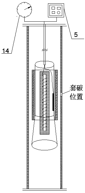
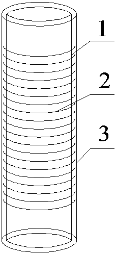
[0034] Such as figure 1 A downhole controllable self-expanding casing supplementary pipe shown, including such as figure 2 , 3 Subsidize the pipe body and as Figure 4 Controllable downhole tool release device;

[0035] Such as figure 2 The subsidy pipe body is composed of a rubber liner 1, a memory alloy ring 2, and a plugging rubber tube 3. The inner surface of the plugging rubber tube 3 is bonded to the outer surface of the rubber liner 1 through a temperature-resistant adhesive. knot, and the outer surface of the plugging rubber cylinder 3 is also coated with a temperature-resistant adhesive; the memory alloy ring 2 is located between the plugging rubber cylinder 3 and the rubber liner 1; the memory alloy ring 2 is made of shape memory alloy The material is processed. Shape memory alloy material can produce shape memory effect after component design, preparation and repeated training treatment, and can quickly return to the original memory shape at a specific high t...

Embodiment 2

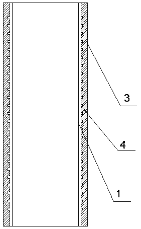
[0040] On the basis of Example 1, such as image 3 Trapezoidal grooves 4 are evenly distributed on the inner wall of the leak-stopping rubber cylinder 3, and the memory alloy ring 2 is embedded in the trapezoidal grooves 4; to the limiting effect. The memory alloy ring 2 is embedded in the trapezoidal groove 4, and the rubber liner 1 and the plugging rubber cylinder 3 are firmly bonded by the temperature-resistant adhesive 4; the shape memory alloy material mainly includes titanium-nickel alloy, iron-nickel alloy, and chromium-nickel alloy Wait. The outer diameter of the shape memory alloy ring 2 is generally Φ38mm-Φ244.5mm. According to the specifications and strength requirements of the bushing to be subsidized, the wall thickness of the memory alloy ring is 3mm-10mm; It is fixedly connected by welding; the controllable downhole tool release device also includes a manometer 14 for detecting the pressure in the well; the centralizing cylinder 12 and the conical limit cylin...

Embodiment 3

[0043] Well Wang X-Y in an oilfield, the well depth is 2130m, the casing size is 139.7mm×9.17mm, the casing damage position is 1580-1582m, and the well temperature is about 55℃. The total length of the downhole tool release device is 10m, the size of the centralizing cylinder is 95mm×3mm, the outer diameter of the upper part of the conical limiting cylinder is 95mm, and the outer diameter of the lower part is 110mm.

[0044] Firstly, according to the service environment such as well temperature, qualified subsidy pipes are processed and trained. The subsidy pipes have a size of 106mm×3mm before self-expansion. After expansion, the outer diameter of the free state can be changed to 125mm and the length is 8 meters. In order to prevent accidents such as sudden expansion due to abnormal well temperature when the subsidy pipe was run in, the self-expansion thixotropic temperature was set at 80°C during the training, which was much higher than the wellbore temperature at the casing ...


PUM


Abstract

The invention relates to an underground controllable self-expansion casing patching pipe which comprises a patching pipe body and a controllable underground tool release device. The patching pipe body is composed of a rubber inner container, a memory alloy ring and a leaking stoppage rubber barrel. The inner surface of the leaking stoppage rubber barrel and the outer surface of the rubber inner container are adhesively connected through a temperature resistance adhesive. The controllable underground tool release device at least comprises a temperature controller, a cable, a heat pipe, a heating winding wire, a stainless steel protective pipe, a thermocouple, a centering barrel and a conical limiting barrel. The stainless steel protective pipe is located inside the centering barrel. The heat pipe is located inside the stainless steel protective pipe. The heating winding wire is evenly wound around the heat pipe. The thermocouple is fixed to the inner wall of the centering barrel. The thermocouple and the heating winding wire are electrically connected with the temperature controller through the cable. The centering barrel is sleeved with the patching pipe body which is clamped to the top of the conical limiting barrel. Casing patching work can be completed without hydraulic expansion or gunpowder explosion or other means, operation is convenient, and construction is safe.

Description

technical field [0001] The invention relates to the technical field of oil well casing repair, in particular to an underground controllable self-expanding casing subsidy pipe. Background technique [0002] After the casing of oil and water wells is damaged due to various reasons, formation water flows back into the oil layer, causing problems such as shutting down of oil and water wells, damage to well pattern and failure to recover remaining oil, which is an important factor affecting the normal production of oil wells. [0003] Many oilfields in the United States and Middle East oil-producing countries began to suffer from casing corrosion and damage since the 1950s. The main control measures adopted include pipe expansion subsidies, sidetracking, and mechanical water shutoff. Since the 1970s, oil fields such as Jilin, Jianghan, Daqing, and Changqing in my country have successively experienced casing damage caused by casing deformation, salt rock creep, and electrochemical...

Claims


Application Information

Patent Timeline
Patent Type & Authority Patents(China)
IPC IPC(8): E21B29/10
CPCE21B29/10
Inventor 奚运涛李琼玮周志平王焕成孙雨来张鑫柱杨会丽苑慧莹李美玉侯金晔
Owner PETROCHINA CO LTD
Learn More