
A top bolt drilling rig and a top bolt drilling rig comprising the same

A technology for top anchor and drilling rig, which is used in the installation of anchor rods, drilling equipment, and earth-moving drilling and mining, etc., can solve the problems of low degree of mechanization, low efficiency and high labor intensity of the single-piece rock-bolt drill. , to solve the contradiction of excavation and anchor imbalance, compact structure and high drilling efficiency

Active Publication Date: 2018-06-05
LANG FANG JING LONG GRAND IND MACHINERY CO LTD
View PDF6 Cites 0 Cited by
  • Summary
  • Abstract
  • Description
  • Claims
  • Application Information

AI Technical Summary

Problems solved by technology

In the roadway excavation operation, the operating rate of the roadheader is only about 30%, and most of the rest of the time is used for support. The low support efficiency is the most important factor affecting the excavation footage
[0003] At present, most of the bolt and cable support operations in large and medium-sized coal mines in my country rely on manual use of hand-held single bolters and coal electric drills, while the single-piece bolter has low mechanization and high labor intensity.
And because the hand-held single bolter is operated by manpower, the limitation of manpower itself causes the locking force of the bolt to be tightened twice, which not only increases the workload, but also takes up a lot of time, and requires workers to work in groups. Hence the inefficiency of monobloc rock bolters

Method used


Image

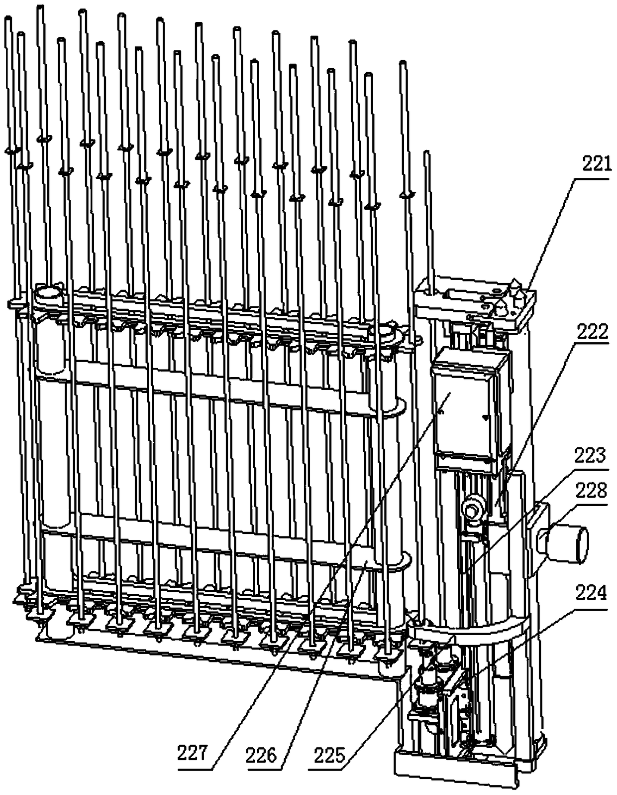
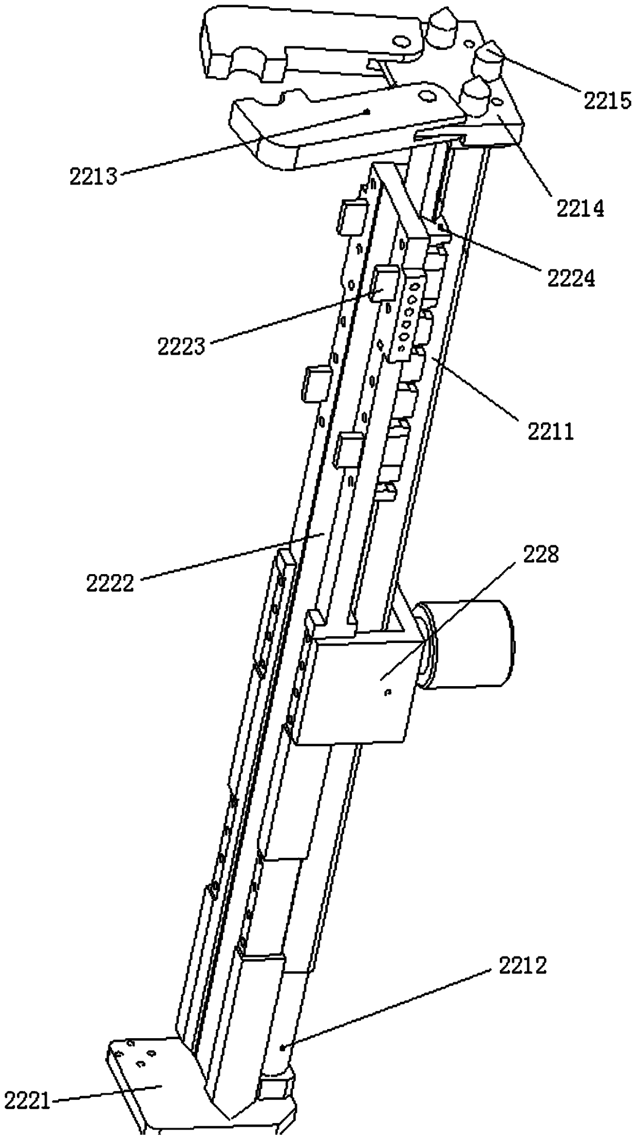
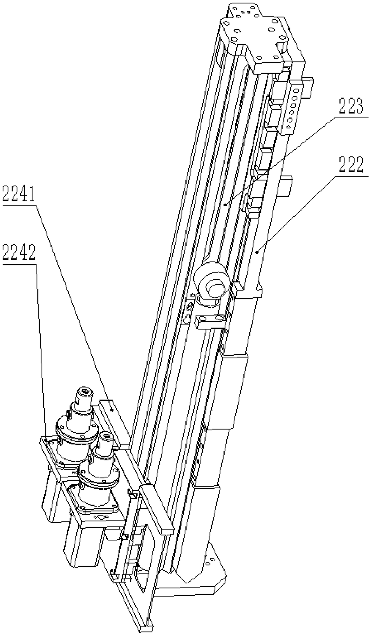
  • A top bolt drilling rig and a top bolt drilling rig comprising the same
  • A top bolt drilling rig and a top bolt drilling rig comprising the same
  • A top bolt drilling rig and a top bolt drilling rig comprising the same

Examples


Embodiment 1

[0069] Embodiment 1: The specific structure of the four-arm top bolter rig comprising the above-mentioned top bolter rig is as follows:

[0070] Refer to attached Figure 6 and 7 As shown, the four-arm top bolt drilling rig includes a self-propelled mechanism 7, a body part 4, a drilling arm mechanism 2, a control mechanism 6, a storage and delivery mechanism 5, a supporting and laying mechanism 1, and an electrical and hydraulic system 3 .

[0071] The self-propelled mechanism 7 is a crawler-type traveling mechanism, which is located at the bottom of the drilling rig, and includes a tightening oil cylinder, a traveling motor and a speed reducer. The tension of the track can be adjusted through the telescopic movement of the tension cylinder; the travel motor drives the reducer, and the track is driven by the sprocket to realize the forward and backward movement of the walking mechanism. The self-propelled mechanism 7 is controlled by the control mechanism 6, and can achiev...

Embodiment 2

[0081] Embodiment 2: The six-arm top bolter comprising the above-mentioned top bolter is further improved on the basis of the above-mentioned four-arm top bolter, and its improvements are as follows:

[0082] Refer to attached Figures 12 to 15 As shown, the drill arm mechanism 2' of the six-arm top bolter rig of the present invention includes a drill arm plate 21', a front slide rail group arranged on the drill arm plate 21', and a rear slide rail set arranged on the lower surface of the lifting platform 45'. Rail group 22' and six top bolt rigs (from left to right are rigs 1 to 6), the drill arm plate 21' is vertically fixed and installed on the lifting platform 45', and the six top bolt rigs are divided into two rows at the front and back Set, and the distance between the front and rear rows of drilling rigs is the distance between one row of bolts. The four top bolt rigs in the front row are lined up horizontally, and they are all installed on the front slide rail group o...


PUM


Abstract

The invention discloses an anchor rod jacking mechanism which comprises a fixing mechanism, a supporting mechanism, a sliding block and a drill box mechanism. The fixing mechanism comprises a base, a stand plate and a connecting seat. Protrusions for fixing guide blocks are arranged on the stand plate. The supporting mechanism and the sliding block are in sliding connection with the opposite side faces of the stand plate through the guide blocks respectively. One end of the supporting mechanism and one end of the slide block are connected with base through telescopic oil cylinders. The drill box mechanism comprises a bottom frame and two independent drill box sliding seats. The bottom frame is connected with the base, and the drill box sliding seats can horizontally move along the bottom frame. When the drill box sliding seats move to the sliding block, the drill box sliding seats can be connected with the other guide rail face of the sliding block and slide along the sliding block. The invention further discloses an anchor rod jacking drilling carriage with a drilling machine. The anchor rod jacking drilling carriage comprises a four-wall anchor rod jacking drilling carriage body and a six-arm anchor rod jacking drilling carriage body. The drilling machine in the anchor rod jacking drilling carriage can work at the same time. Fast supporting operation on a top plate can be achieved, the structure is compact, and multiple functions are achieved. The anchor rod jacking mechanism and the anchor rod jacking drilling carriage operate in cooperation with heading equipment to complete the supporting and transferring function synchronously, operating personnel are greatly reduced, the labor intensity is lowered, and the supporting efficiency and safety are improved.

Description

technical field [0001] The invention relates to the technical field of coal mine underground support, in particular to a top-bolt drilling rig and a top-bolt drilling vehicle comprising the drilling rig. Background technique [0002] The unbalanced state of anchor excavation in my country's coal mines is relatively serious, and the support speed cannot keep up with the excavation speed, which has become a bottleneck restricting the development of rapid excavation technology. In the roadway excavation operation, the operating rate of the roadheader is only about 30%, and most of the rest of the time is used for support. The low support efficiency is the most important factor affecting the excavation footage. [0003] At present, most of the bolt and cable support operations in large and medium-sized coal mines in my country rely on manual use of hand-held single bolters and coal electric drills, while the single-piece bolter has low mechanization and high labor intensity. An...

Claims


Application Information

Patent Timeline
Patent Type & Authority Patents(China)
IPC IPC(8): E21B7/02E21B15/00E21D20/00
CPCE21B7/02E21B7/022E21B15/00E21D20/003
Inventor 蒲长晏武利民卢道林韩非刘芳刘琦张国忠景志国闫子龙王明磊
Owner LANG FANG JING LONG GRAND IND MACHINERY CO LTD
Learn More