
Locking device for high and low voltage switchgear

A technology of high and low voltage switches and locking devices, which is applied in the direction of electric switches, electrical components, circuits, etc., can solve the problems of not installing a built-in package sealing structure, poor waterproof performance of the locking device, and unable to lock the device to pop up, so as to improve the use effect and latching performance, improving safety and practicality, and reducing the probability of safety failure

Pending Publication Date: 2019-05-24
江苏宏强电气集团有限公司
View PDF0 Cites 0 Cited by
  • Summary
  • Abstract
  • Description
  • Claims
  • Application Information

AI Technical Summary

Problems solved by technology

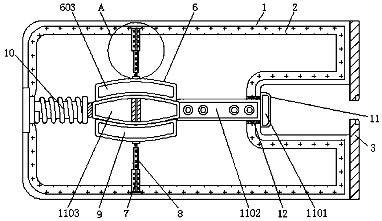
[0004] The purpose of the present invention is to provide a locking device for high and low voltage switchgear, to solve the problem that the structure of the locking device for switchgear on the market proposed in the background technology is relatively complicated, and the locking performance cannot be realized through a simple mechanical structure, and the production cost is relatively high. , when maintenance and repairs are required, the parts cannot be replaced directly in the locking device by disassembling the structure, and there is no built-in wrapping sealing structure. The waterproof performance of the locking device is poor. The locking device pops up, which is time-consuming and labor-intensive in operation

Method used


Image

  • Locking device for high and low voltage switchgear
  • Locking device for high and low voltage switchgear
  • Locking device for high and low voltage switchgear

Examples


Embodiment Construction

[0019] The following will clearly and completely describe the technical solutions in the embodiments of the present invention with reference to the accompanying drawings in the embodiments of the present invention. Obviously, the described embodiments are only some, not all, embodiments of the present invention. Based on the embodiments of the present invention, all other embodiments obtained by persons of ordinary skill in the art without making creative efforts belong to the protection scope of the present invention.

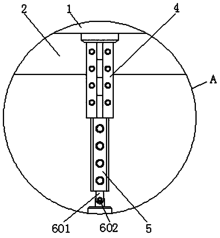
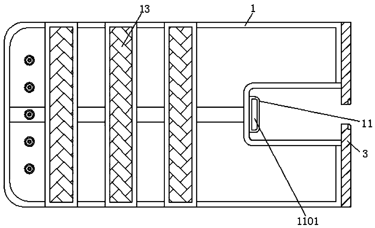
[0020] see Figure 1-3 , the present invention provides a technical solution: a locking device for high and low voltage switchgear, including a main body 1, an insulating gasket 2, a limit plate 3, a first hydraulic rod 4, a first telescopic rod 5, a disassembly assembly 6, a connecting Block 601, connecting bolt 602, first conductor block 603, second hydraulic rod 7, second telescopic rod 8, second conductor block 9, return spring 10, movable assembly 11, man...


PUM


Abstract

The invention discloses a locking device for a high and low voltage switchgear, comprising a main body, an insulating sealing gasket and a second hydraulic rod, wherein one side of the main body is fixedly welded with a limiting plate; the upper end of the inner wall of the main body is fixedly welded with a first hydraulic rod; the lower end of the first hydraulic rod is connected with a first telescopic rod through a key; the lower end of the first telescopic rod is provided with a disassembling assembly; the insulating sealing gasket is adhesively fixed to the outer side of the first hydraulic rod; the second hydraulic rod is fixedly welded on the bottom part of the inner wall of the main body; and the upper end of the second hydraulic rod is connected with a second telescopic rod through a key. According to the locking device for the high and low voltage switchgear, the structure is simpler, the locking performance can be realized through a simple mechanical structure, the production cost is lower, mass production and use are facilitated, and when maintenance is needed, part replacement can be directly carried out in the locking device through the disassembling structure, and when the switchgear is used normally, the locking device can be ejected through a reset structure, and more time and labor are saved in operation and use.

Description

technical field [0001] The invention relates to the technical field of locking devices for switch cabinets, in particular to a locking device for high and low voltage switch cabinets. Background technique [0002] As the name suggests, the high and low voltage switchgear is a device for connecting high-voltage or low-voltage cables. Generally, power supply bureaus and substations use high-voltage cabinets, which are then stepped down by transformers to low-voltage cabinets, and then to various power distribution boxes. It is nothing more than an electrical equipment assembled with some protective devices such as switch circuit breakers. The locking device for the switch cabinet mainly realizes five anti-functions: preventing load and closing the disconnector; preventing closing with the grounding wire, etc. The mechanical lock is the switch The mechanical structure of the equipment operating mechanism restricts each other, so as to achieve the interlocking locking mode. [...

Claims


Application Information

Patent Timeline
Patent Type & Authority Applications(China)
IPC IPC(8): H01H9/20
Inventor 陶文祥
Owner 江苏宏强电气集团有限公司
Learn More