
Needling machine rack with guiding and supporting functions to needle plate

A needle punching machine and needle board technology, which is applied in the direction of needle punching machines, textiles, papermaking, non-woven fabrics, etc., can solve the problems of endangering the safety of equipment maintenance personnel, slow movement, and economic losses, so as to improve operating efficiency and reduce The effect of manpower input and avoiding economic loss

Active Publication Date: 2016-03-30
JIANGSU YINGYANG NONWOVEN MASCH CO LTD
View PDF8 Cites 0 Cited by
  • Summary
  • Abstract
  • Description
  • Claims
  • Application Information

AI Technical Summary

Problems solved by technology

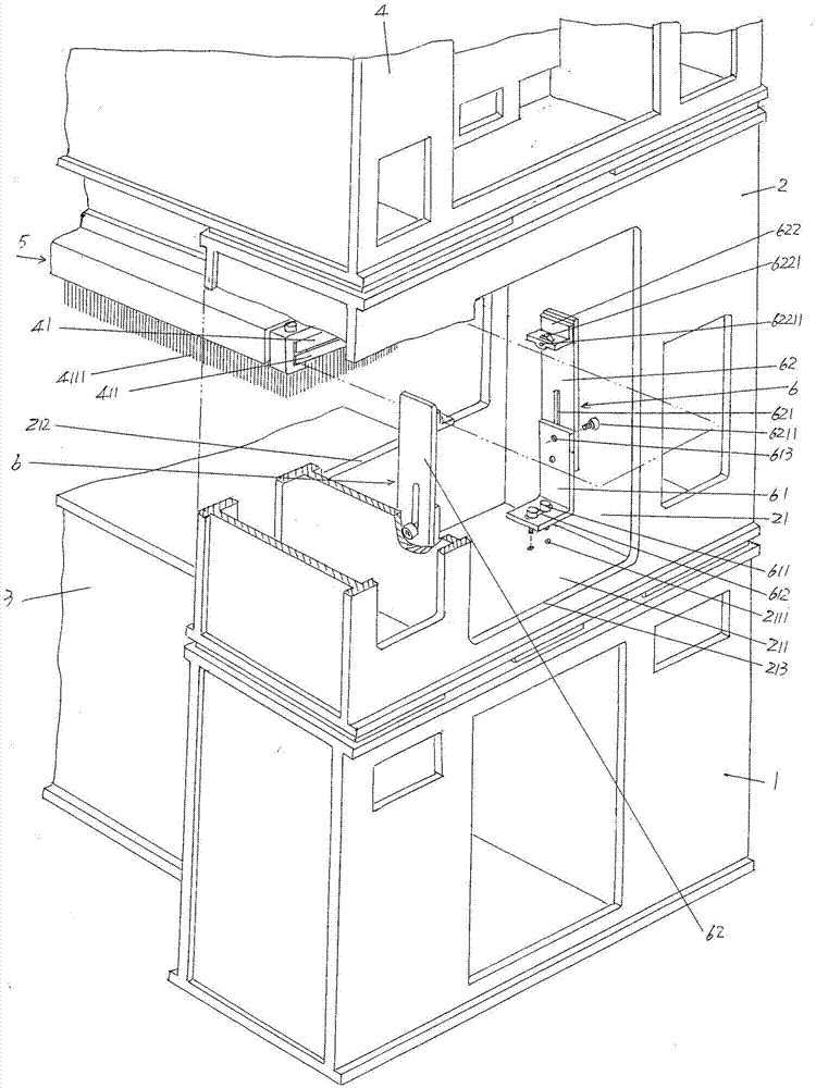
[0004] Furthermore, as known in the industry, the length of the effective needling area of ​​the needle board needs to be compatible with the width (width) of the non-woven product, that is to say, the larger the width of the non-woven product, the longer the length of the needle board (including the needle beam). It is also correspondingly longer, so there are the following unavoidable technical problems in the following three aspects in the process of pulling the needle plate outwards or pushing it inward through the aforementioned needle plate relief hole: one, because in order to avoid damaging the needle The needles on the board need to be carried by multiple people to work together to keep the needle board suspended from the bottom edge of the needle board chamber, which not only increases the operating strength of the equipment maintenance personnel, but also requires a lot of manpower and The movement is slow; secondly, taking the needle plate pulled out as an example, as the length of the needle plate drawn out increases, the cantilever end of the needle plate will drop. If the support is neglected at this time, the needle plate may break , causing economic losses at the slightest, and at the worst, it will have a safety impact on the equipment maintenance personnel. The same example is inserted into the needle plate when it is loaded. In view of this, the industry says that replacing the needle plate or rearranging the needles on the needle plate is an extremely high-risk operation; the third In the process of pulling out the needle plate and at the moment when the end of the needle plate is completely separated from the needle plate fixing frame, if the protection is neglected, it will suddenly collide with the bottom edge of the needle plate relief cavity, so there is also damage and the needle plate or endanger the safety of equipment maintenance personnel

Method used


Image

  • Needling machine rack with guiding and supporting functions to needle plate
  • Needling machine rack with guiding and supporting functions to needle plate
  • Needling machine rack with guiding and supporting functions to needle plate

Examples


Embodiment Construction

[0017] In order to enable the examiners of the patent office, especially the public, to understand the technical essence and beneficial effects of the present invention more clearly, the applicant will describe in detail the following in the form of examples, but none of the descriptions to the examples is an explanation of the solutions of the present invention. Any equivalent transformation made according to the concept of the present invention which is merely formal but not substantive shall be regarded as the scope of the technical solution of the present invention.

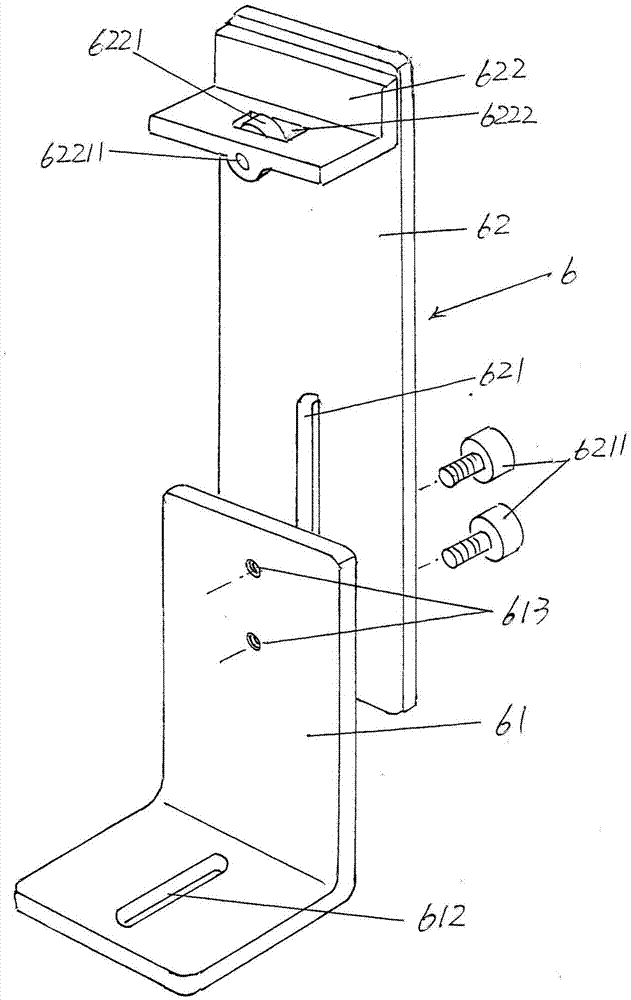
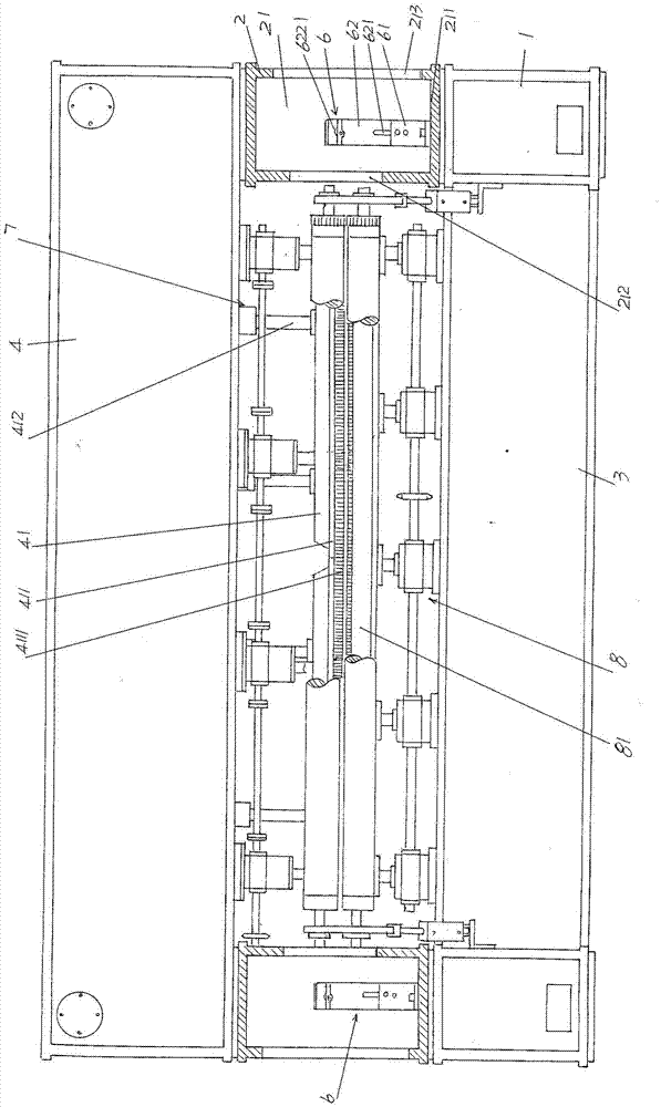
[0018] See figure 1 , showing a pair of bottom box bodies 1, a pair of middle column box bodies 2 and a bottom box girder 3 arranged facing each other, and a pair of middle column box bodies 2 are respectively arranged on the sides of a pair of bottom box bodies 1 top, and a needle plate relief cavity 21 is provided on the pair of middle column box bodies 2, and the bottom box beam 3 is fixed between the pair...


PUM


Abstract

The invention provides a needling machine rack with guiding and supporting functions to a needle plate, and belongs to the technical field of non-textile machines. The needling machine rack comprises a pair of bottom case bodies, a pair of middle stand column case bodies and a bottom case beam, the middle stand column case bodies are arranged on the tops of the corresponding bottom case bodies, a needle plate receding cavity is formed in each middle stand column case body, the bottom case beam is fixed between the bottom case bodies, a crankshaft case body is arranged on the portion corresponding to the upper portions of the middle stand column case bodies, a needle beam is arranged below the crankshaft case body and connected with a crankshaft connecting rod mechanism, the needle plate is arranged on the lower portion of the needle beam, the two sides in the length direction of the needle plate are fixed with the needle beam, and the ends of the needle plate correspond to the needle plate receding cavities. The needling machine rack with the guiding and supporting functions to the needle plate has the advantages that a needle plate guiding and supporting mechanism is arranged on the portion, corresponding to the position of the corresponding needle plate receding cavity, of each middle stand column case body; human input is reduced, operating intensity is reduced, and the efficiency is improved; accidental fracture of the needle plate can be prevented, economic losses can be avoided, damage to operating personnel can be avoided, and the operating safety is guaranteed.

Description

technical field [0001] The invention belongs to the technical field of non-woven machinery, and in particular relates to an acupuncture machine frame with the function of guiding and supporting a needle plate. Background technique [0002] The function of the needle punching machine is to entangle and stab the non-woven fibers to form the required non-woven products, such as non-woven fabrics, non-woven felts, non-joint industrial wool (no joints, that is, non-end industrial wool, such as papermaking felt, various conveyor belts, etc.). There are three main structural forms of the acupuncture machine frame: one is composed of a pair of wall panels facing each other and a wall panel connecting beam connected between the pair of wall panels to make the pair of wall panels form a whole. Such as the "dislocation puncture needle machine" recommended by the Chinese Patent Authorization Announcement No. CN2421298Y; the second is set up facing each other and each consists of a bott...

Claims


Application Information

Patent Timeline
Patent Type & Authority Applications(China)
IPC IPC(8): D04H18/02
Inventor 范立元
Owner JIANGSU YINGYANG NONWOVEN MASCH CO LTD
Learn More