Machining method of supporting sleeve and supporting sleeve

A processing method and technology of support sleeve, which are applied in the direction of fluid pressure actuating device, etc., can solve the problems of affecting the working efficiency and service life of the breaker, affecting the matching clearance between the copper sleeve and the piston, increasing the processing cost of the support sleeve, etc., so as to reduce the processing cost. Cost, good guiding and supporting effect, and the effect of convenient processing

Pending Publication Date: 2021-02-19
YANTAI AIDI PRECISION MASCH CO LTD
View PDF1 Cites 1 Cited by
  • Summary
  • Abstract
  • Description
  • Claims
  • Application Information

AI Technical Summary

Problems solved by technology

[0006] The copper sleeve on the existing support sleeve is processed by cold packing. Specifically, the copper sleeve is frozen to shrink the copper sleeve by 0.1-0.4mm, and then put into the support sleeve, and the copper sleeve expands by thermal expansion and cold contraction. Interference fit with the support sleeve, in order to ensure that the expansion of the copper sleeve can be closely matched with the support sleeve, the thickness of the copper sleeve is relatively large, generally the thickness of the copper sleeve is 5mm-10mm, which increases the processing cost of the support sleeve; The bonding strength between the sleeve and the support sleeve is often insufficient. During the high-speed movement of the piston, the copper sleeve is easy to loosen and separate from the support sleeve, causing the copper sleeve and the piston to lock up. In addition, the thermal expansion coefficient of steel is smaller than that of copper. In addition, the larger the thickness of copper, the larger the expansion will be, which will affect the fit gap between the copper sleeve and the piston, which cannot meet the requirements of the fit gap between the copper sleeve and the piston, will hinder the movement of the piston, and seriously affect the crushing. Working efficiency and service life of the hammer

Method used


Image

  • Machining method of supporting sleeve and supporting sleeve
  • Machining method of supporting sleeve and supporting sleeve
  • Machining method of supporting sleeve and supporting sleeve

Examples


Embodiment 1

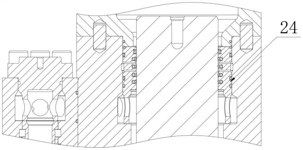
[0064] Example 1, such as Figure 5-Figure 12 As shown, a processing method for a support sleeve includes the following steps:

[0065] 1) Process the support sleeve base 1 and the annular retaining ring 2, and process the ring platform 11 and the inclined surface 12 on the support sleeve base;

[0066] 2) Fix the annular retaining ring 2 on the ring platform 11, so that an annular cavity 3 is formed between the annular retaining ring 2 and the support sleeve base 1;

[0067] 3) Copper alloy or copper material is evenly distributed on the upper part of the annular cavity, and then the support sleeve matrix with copper alloy or copper material is placed in a sintering furnace for sintering. The sintering temperature is 1000-1150 degrees, and the sintering time is 2-5h, the copper sleeve blank 4 is formed in the annular cavity after the copper alloy or copper material is sintered;

[0068] 4) Machining to form a semi-finished support sleeve;

[0069] 5) nitriding treatment, p...

Embodiment 2

[0077] Example 2, such as Figure 13 As shown, the inner diameter of the ring seat processed in step 1) is smaller than the outer diameter of the annular retaining ring. In this case, the annular retaining ring can be fixed directly on the ring platform. The rest of the steps are the same as in Example 1 and will not be repeated here.

Embodiment 3

[0078] Example 3, such as Figure 14 As shown, step 1) also includes processing at least one ring groove 13 on the support base. The melting of copper alloy or copper material can enter the ring groove, further increasing the bonding strength between the copper sleeve and the base of the support sleeve. The rest of the steps are the same as in Example 1 and will not be repeated here.

[0079] At least one annular groove 17 is provided on the base of the support sleeve processed by the embodiment 3, and an annular protrusion matching the annular groove is provided on the copper sleeve. The tight combination between the copper sleeve and the supporting sleeve base further increases the bonding strength between the copper sleeve and the supporting sleeve base to prevent the loosening of the copper sleeve, thereby preventing the wear between the piston and the cylinder and prolonging the service life of the breaker.


PUM


Abstract

The invention discloses a machining method of a supporting sleeve and the supporting sleeve. The machining method of the supporting sleeve comprises the following steps of (1) machining a supporting sleeve base body and an annular check ring; 2) fixing the annular check ring on an annular table, so that an annular cavity is formed between the annular check ring and the supporting sleeve base body;3) melting a copper alloy or a copper material into the annular cavity to form a copper sleeve blank in the annular cavity; 4) machining to form a supporting sleeve semi-finished product; 5) nitriding treatment; and 6) finish machining. According to the machining method, copper alloy or copper materials are placed in the annular cavity or on the upper portion of the annular cavity in the step (3), then the supporting sleeve base body containing the copper alloy or the copper materials is placed in a sintering furnace to be sintered, the supporting sleeve comprises the supporting sleeve base body and a copper sleeve, and the supporting sleeve is machined through the machining method of the supporting sleeve; and machining is convenient, the bonding strength between the copper sleeve and the supporting sleeve base body is improved, the copper sleeve is not prone to loosening, collision between a piston and a cylinder body is avoided, the service life of a breaking hammer is prolonged, and the machining cost of the supporting sleeve is reduced.

Description

technical field [0001] The invention relates to a processing method of a support sleeve and the support sleeve, belonging to the technical field of mechanical processing. Background technique [0002] The breaker is an important working tool of the hydraulic excavator. It is a machine tool that can convert hydraulic energy into mechanical energy to do work externally. It uses hydrostatic pressure as the power to drive the internal piston to reciprocate. When the piston strokes, it hits the drill at high speed. The rod is used to crush ore, concrete and other solids by the drill rod, and is used for crushing, demolition and other work. [0003] In order to meet the installation of the piston of the breaker and avoid hydraulic oil leakage, an oil seal holder is set between the upper cylinder of the breaker and the piston, such as figure 1 and figure 2 Shown is an existing one-piece oil seal holder structure, the lower part of the oil seal holder has an annular part for buff...

Claims


Application Information

Patent Timeline
IPC IPC(8): B23P15/00F15B15/20
CPCB23P15/00F15B15/1423
Inventor 傅贻文宋飞宋雷刚徐尚武张伟郭英鉴
Owner YANTAI AIDI PRECISION MASCH CO LTD
Why Eureka
Try Eureka