
Photocatalyst honeycomb subassembly, and photocatalyst purifier

A honeycomb assembly and purification device technology, applied in chemical instruments and methods, dispersed particle separation, irradiation, etc., can solve the problems of large air flow resistance, failure to meet the flow resistance requirements, and the actual effect to be verified, etc., to improve the contact area effect

Active Publication Date: 2016-03-30
COMAC +1
View PDF4 Cites 6 Cited by
  • Summary
  • Abstract
  • Description
  • Claims
  • Application Information

AI Technical Summary

Problems solved by technology

[0014] However, the photocatalyst devices of the single channel type extended surface type in the above three situations all have the following disadvantages: the air flowing in the channel will be subjected to a large flow resistance, and in the field of ventilation systems that are more sensitive to the flow resistance, such as vehicles. In ventilation systems, flow resistance requirements are likely not met
[0019] However, the photocatalyst device of the superimposed honeycomb flow channel of the above three situations also has the following disadvantages: the air flowing in the flow channel will be subject to a large flow resistance. In the field of ventilation systems that are more sensitive to flow resistance, such as the ventilation of vehicles system, it is likely that the flow resistance requirements will not be met
However, this idea has not been realized in kind, and its actual effect remains to be verified

Method used

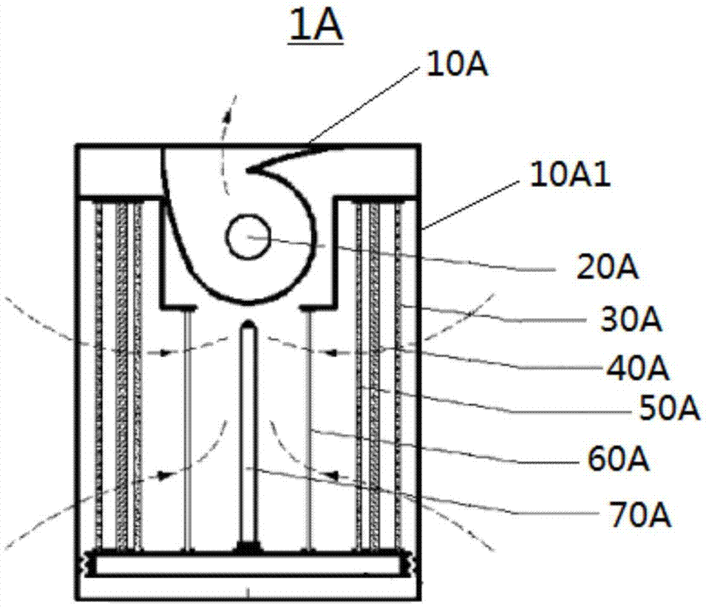
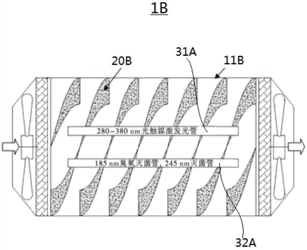
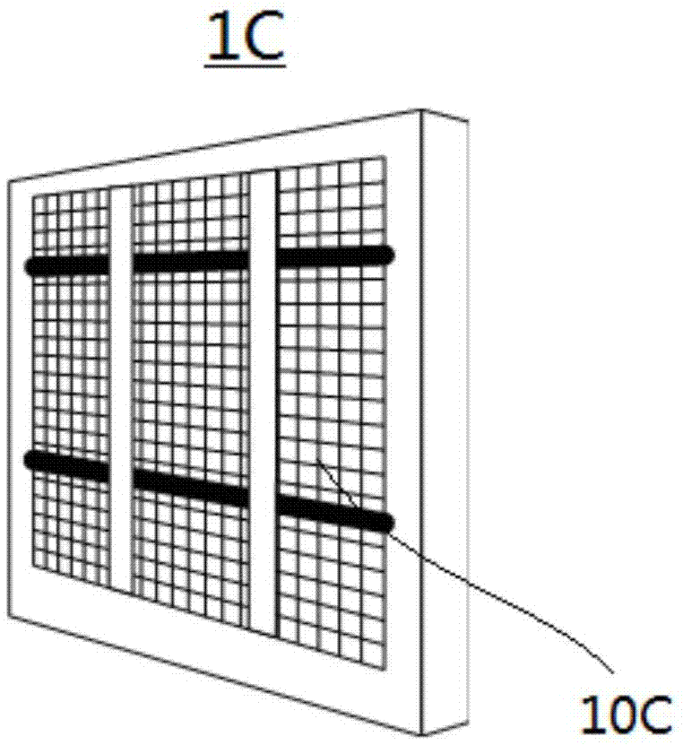

Image

  • Photocatalyst honeycomb subassembly, and photocatalyst purifier
  • Photocatalyst honeycomb subassembly, and photocatalyst purifier
  • Photocatalyst honeycomb subassembly, and photocatalyst purifier

Examples


Embodiment 1

[0080] refer to Figure 10 and Figure 11 , Embodiment 1 of the photocatalyst honeycomb component 100 of the present invention will be described. Figure 10 will be Figure 9 An expanded view of an embodiment of the photocatalyst honeycomb filter element 110 in the photocatalyst honeycomb assembly 100 shown. Figure 11 is expressed in Figure 8 The diagram showing the reflection of light in the hexagonal air channel 112 of the photocatalyst honeycomb filter element 110 of the photocatalyst honeycomb assembly 100 is shown.

[0081] As mentioned in the analysis of the prior art in the background art, considering the limitations of the irradiation range of the light source, there is a problem that the light source cannot effectively irradiate the inside of the photocatalyst honeycomb filter element 110 . The longer the length of the photocatalyst honeycomb filter element 110 in the axial direction of the photocatalyst honeycomb assembly 100 is, the more serious this problem i...

Embodiment 2

[0093] Next, refer to Figure 13 and 12 , Embodiment 2 of the photocatalyst honeycomb component 100 of the present invention will be described. Figure 13 It is a partial schematic view of embodiment 2 of the photocatalyst honeycomb assembly 100 used in the photocatalyst purification device 10 of the pipeline type of the present invention, which shows a part of the photocatalyst honeycomb filter core 110 ' of the photocatalyst honeycomb assembly 100. Figure 14 yes means Figure 13 The schematic diagram of the light guide member 115' in the photocatalyst honeycomb filter element 110' shown.

[0094] The difference between this embodiment 2 and the above-mentioned embodiment 1 is that in the above-mentioned embodiment 1, such as Figure 10 As shown, each filter core basic unit 111 is made of six coating surfaces, and a plurality of filter core basic units 111 are configured in a honeycomb shape to form a photocatalyst honeycomb filter core 110, but in the present embodiment ...

Embodiment 3

[0101] Next, refer to Figures 15 to 16 , Embodiment 3 of the photocatalyst honeycomb component 100 of the present invention will be described. Figure 15 is indicative of Figure 9 The schematic diagram of the air flow flowing in the hexagonal air channel 112 of the photocatalyst honeycomb filter element 110 of the photocatalyst honeycomb assembly 100 shown. Figure 16 It is a schematic diagram of embodiment 3 of the photocatalyst honeycomb assembly 100 used in the pipeline-type photocatalyst purification device 10 of the present invention, which shows a plurality of photocatalyst honeycomb filter cores 110 "a, 110 "b of the photocatalyst honeycomb assembly 100 Forms that are staggered from each other. Figure 17 It means viewing along the end viewing direction Figure 16 A diagram of the interlaced surfaces of the multiple photocatalyst honeycomb filter cores 110"a, 110"b shown. Figure 18 It is a schematic diagram showing the air flow flowing in the hexagonal air channe...


PUM


Abstract

The invention discloses a photocatalyst honeycomb subassembly. The photocatalyst honeycomb subassembly is capable of enlarging the contact area of polluted air with photocatalysts as far as possible, ensuring sufficient light irradiation of photocatalyst surfaces is achieved as far as possible, and at the same time allowing flow resistance of air flow in flow channels to satisfy ventilation systems with relatively high requirements on flow resistance. The photocatalyst honeycomb subassembly comprises a photocatalyst honeycomb subassembly housing, and one or a plurality of photocatalyst honeycomb filter elements; each photocatalyst honeycomb filter element is composed of a plurality of filter element elementary units arranged in a honeycomb manner; the filter element elementary units are polygonal or circular from axial view; one part of the polygonal or the circular internal surface, or the whole polygonal or the circular internal surface of each filter element elementary unit is coated with a photocatalyst coating layer; and polygonal or circular air channels, used for flowing of air, are formed by encircling of the polygonal or the circular internal surfaces of the filter element elementary units.

Description

technical field [0001] The invention relates to a photocatalyst honeycomb component and a photocatalyst purification device. More specifically, the invention relates to a photocatalyst purification device which utilizes the principle of photocatalyst to purify air and the photocatalyst honeycomb component therein. Background technique [0002] Photocatalyst is a substance that does not change itself under the irradiation of light, but can promote chemical reactions. Under the irradiation of light, the photocatalyst can activate the oxygen and water adsorbed on the surface of the material, produce free hydroxyl groups and active oxygen with strong oxidizing ability, and undergo an oxidation reaction to completely decompose organic matter, bacteria, viruses, etc. into carbon dioxide and water. [0003] Photocatalyst air purification technology is an ideal technology for controlling environmental pollution in the world. Among them, the key to the excellent purification effect...

Claims


Application Information

Patent Timeline
Patent Type & Authority Applications(China)
IPC IPC(8): A61L9/20A61L9/18B01D53/86B01D53/44
CPCA61L9/18A61L9/20B01D53/44B01D53/86A61L9/205B01D53/8687B01D53/885
Inventor 程湛史乔升况薇张存任重远汪光文简夕忠吴成云孙学德江娜杨智
Owner COMAC
Learn More