
NNI PING realization method and device

An implementation method and equipment technology, applied in the field of communication, can solve problems such as single detection effect, no solution proposed, single detection effect of NNIPING, etc., and achieve the effect of increasing capacity

Active Publication Date: 2016-03-23
ZTE CORP
View PDF6 Cites 17 Cited by
  • Summary
  • Abstract
  • Description
  • Claims
  • Application Information

AI Technical Summary

Problems solved by technology

[0008] It can be seen that this kind of scene detection effect is relatively simple, and it can only detect the connectivity between device C and device A.
[0009] Aiming at the problem of single detection effect of NNIPING in related technologies, no effective solution has been proposed yet

Method used


Image

  • NNI PING realization method and device
  • NNI PING realization method and device
  • NNI PING realization method and device

Examples


Embodiment Construction

[0029] Hereinafter, the present invention will be described in detail with reference to the drawings and examples. It should be noted that, in the case of no conflict, the embodiments in the present application and the features in the embodiments can be combined with each other.

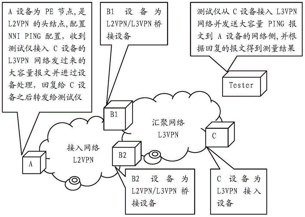
[0030] The inventors found that, if an access device C in the above-mentioned L3VPN network continuously sends large-capacity NNIPING packets, for example, it may be a User Datagram Protocol (UDP) response protocol (EchoProtocol) , referred to as echo, mainly used for debugging and detection) packets, after being processed by the head node PE device A of the L2VPN and returned to the C device, and then through the reception of the message of the tester or computer terminal connected to the C device , you can get other useful information, such as network throughput, packet loss rate, jitter and other performance indicators between the above two devices.

[0031] Based on the above considerations, in ...


PUM


Abstract

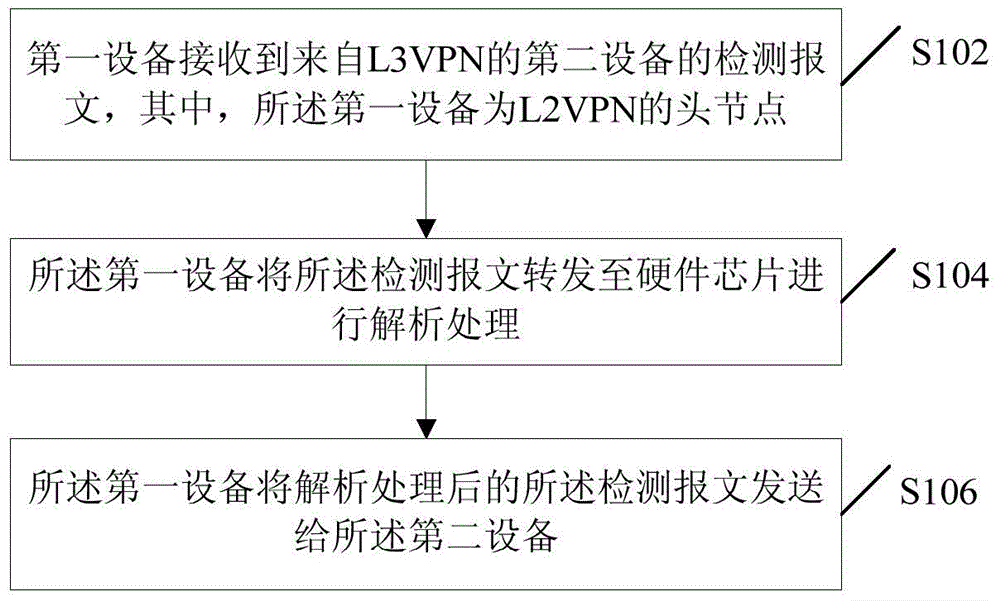
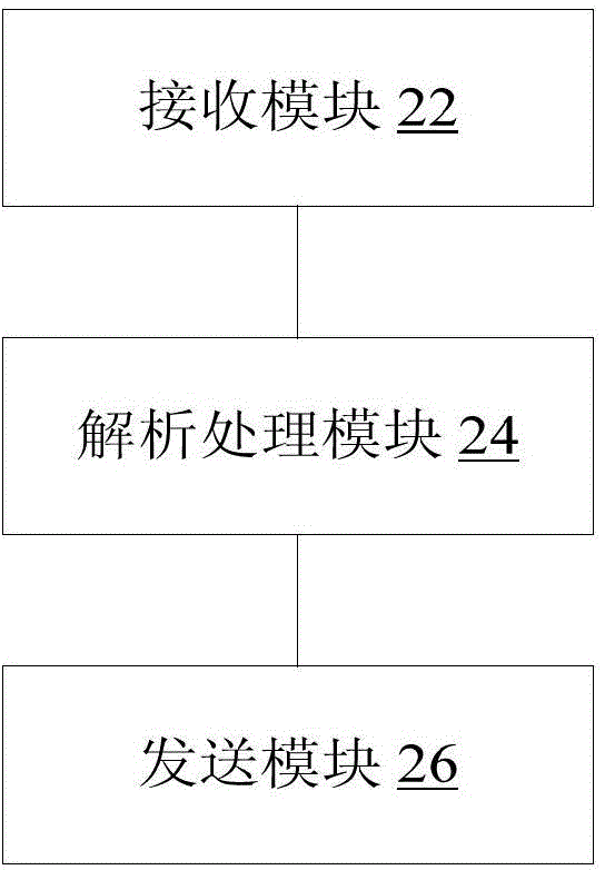
The invention discloses an NNI (Network Node Interface) PING realization method and device. The method comprises the following steps: first equipment receives a detection message of second equipment from an L3VPN (layer3Virtual Private Network), the first equipment being a PE (Provider Edge) of an L2VPN; the first equipment forwards the detection message to a hardware chip for analysis; and the first equipment sends the detection message that has been analyzed to the second equipment. The problem of only a single detection effect of an NNI PING in the associated technology is solved, so the capacity, processing depth and processing efficiency of the detection message can be greatly improved, and then the second equipment can obtain, besides determining connectivity, other types of useful information such as the network throughput, packet loss ratio, jitter and other performance indexes between the above two pieces of equipment on the basis of received detection messages with higher capacity.

Description

technical field [0001] The present invention relates to the communication field, in particular, to a method and device for implementing a Network Node Interface (NNI for short) PING. Background technique [0002] In the Layer 2 Virtual Private Network (Layer 2 Virtual Private Network, L2VPN for short) / Layer 3 Virtual Private Network (Layer 3 Virtual Private Network, L3VPN for short) bridging network, operators often make a connection between certain devices between the aggregation layer network and the access layer network. Check whether the network is connected. There will be such an application scenario, that is, an access device C in the L3VPN network sends a PING message to the head node of the L2VPN (ProviderEdge, referred to as PE, an edge device in the backbone network, which is directly connected to the user's CE, Responsible for the distribution of user routes and the management of VRF routing tables. The forwarding layer implements the encapsulation and decapsulat...

Claims


Application Information

Patent Timeline
IPC IPC(8): H04L12/46
CPCH04L12/46
Inventor 刘志荣
Owner ZTE CORP
Learn More