Multifunctional coupling/decoupling network

A decoupling and multi-functional technology, applied in measuring devices, instruments, measuring interference from external sources, etc., can solve problems such as user inconvenience and increased cost, and achieve the effect of convenient operation, low cost and high degree of integration

Active Publication Date: 2016-03-23
HANGZHOU EVERFINE INSTRUMENT CO LTD
View PDF4 Cites 7 Cited by
  • Summary
  • Abstract
  • Description
  • Claims
  • Application Information

AI Technical Summary

Problems solved by technology

Since the existing coupling and decoupling network can only achieve coupling and decoupling for one coupling path (such as asymmetric or symmetric) of one input waveform, it is inevitable that the user will perform different types of coupling path tests on the same test waveform or When performing the same type or different types of coupling path tests on different test waveforms, it is necessary to select the coupling and decoupling network one by one according to each test waveform and the required coupling path and coupling method to meet the test requirements, which not only increases the user's cost , and caused great inconvenience to users

Method used


Image

  • Multifunctional coupling/decoupling network
  • Multifunctional coupling/decoupling network
  • Multifunctional coupling/decoupling network

Examples


Embodiment 1

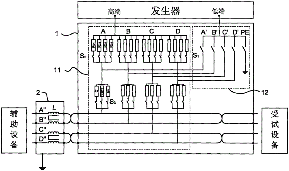
[0039] This embodiment discloses a schematic structural diagram of a coupling and decoupling network, such as image 3 As shown, it includes a coupling circuit 1 and a decoupling circuit 2; the coupling circuit 1 is composed of a coupling high-end line 11 and a coupling low-end line 12, and the coupling high-end line 11 includes four lines connected in parallel, denoted as A, B, C, D , its common end is connected to the high-end of the waveform generator, and each coupling high-end line 11 is connected to the corresponding interface of the decoupling circuit 2 and the device under test respectively through a current-limiting resistor array and a high-end coupling device array connected in series; the decoupling circuit 2 contains four lines, denoted as A", B", C", D", one end of each decoupling line is connected to the corresponding coupling high-end line 11 (A" line is connected to A line, B" line is connected to B line connection, other lines are similarly connected), the ot...

Embodiment 2

[0048] Such as Figure 12 As shown, the difference from Embodiment 1 is that the switching of the current-limiting resistor array, the high-end coupling device array, and the coupling low-end line in this embodiment are all realized by multi-contact relay switches, and the coupling low-end line 12 is set A multi-contact relay switch S 1 , each current-limiting resistor array and high-side coupling device array are respectively provided with a multi-contact relay switch S 2 and multi-contact relay switches S 3 . The connection mode of concrete test can refer to embodiment 1 and table 1.

Embodiment 3

[0050] Such as Figure 13 and Figure 14 As shown, what is different from Embodiments 1 and 2 is that in this embodiment, except for the grounding line PE in the coupling low-end lines 12, each line is respectively connected to n-way coupling high-end lines through a low-end coupling device array. Connection; the node of each low-end coupled line and its corresponding high-end coupled line is located between the coupled high-end line 11 high-end coupling device array and the decoupling line.

[0051] The low-side coupling device array in the coupled low-side line 12 is composed of a gas discharge tube and a 0Ω resistor connected in parallel. in Figure 13 The switchable mode in is realized by ordinary switch, Figure 14 The switchable mode in is realized by multi-contact relay. For the connection mode of the specific test, refer to Embodiment 1 and Table 2. In Table 2, "high end" refers to a high-end coupling device, and "low end" refers to a low-end coupling device.

[0...


PUM


Abstract

The invention discloses a multifunctional coupling / decoupling network, which comprises a coupling circuit and a decoupling circuit, wherein the coupling circuit is provided with multiple paths of coupling circuit high-end lines and coupling low-end lines, and each path of coupling circuit high-end line is serially provided with a switchable current-limiting resistor array comprising various resistance values and a switchable coupling device array comprising various types of coupling elements. When in test, coupling devices, current-limiting resistors and coupling paths are flexibly combined according to different input waveforms, coupling paths and coupling methods, and the unshielded symmetric and asymmetric tests of various kinds of test waveform signal ports including surge waves, ringing waves, damped oscillation waves and the like can be achieved. The multifunctional coupling / decoupling network has the advantages of high integration degree, low cost, convenient operation, wide application range and the like.

Description

【Technical field】 [0001] The invention belongs to the field of electromagnetic compatibility (EMC) testing, and in particular relates to a coupling and decoupling network. 【Background technique】 [0002] With the continuous development of electronic and electrical technology, the electromagnetic environment in which electronic equipment is located is becoming increasingly complex. In order to test the anti-interference ability of the equipment during actual operation, waveform generators such as surge waves 1.2 / 50μs (8 / 20μs), 10 / 700μs (5 / 320μs), ringing wave, damped oscillatory wave and other types of interference waves are injected into the equipment under test through conductive media (such as signal lines, etc.) to evaluate the immunity level of electrical equipment to input waveforms. [0003] The role of the coupling and decoupling network is to couple the interference waveform to the cable connecting the equipment under test, while avoiding adverse effects on auxiliar...

Claims


Application Information

Patent Timeline
Patent Type & Authority Applications(China)
IPC IPC(8): G01R31/00
CPCG01R31/001
Inventor 季军凃辛雅黄英潘建根
Owner HANGZHOU EVERFINE INSTRUMENT CO LTD
Why Eureka
Try Eureka