
Laser marking galvanometer scanning system based on machine vision

A laser marking and machine vision technology, applied in the field of laser marking galvanometer scanning system, can solve the problems of difficult to improve the overall efficiency, difficult to achieve automation, and restrict the development and application of laser marking technology, and achieve a high degree of automation and convenience. Recognition, stabilization and high precision

Inactive Publication Date: 2016-03-23
广东顺德华焯机械科技有限公司
View PDF5 Cites 23 Cited by
  • Summary
  • Abstract
  • Description
  • Claims
  • Application Information

AI Technical Summary

Problems solved by technology

[0005] Compared with other marking technologies, it has the characteristics of fast speed, no contact, less damage, and rich visual effects. However, with the continuous development of laser technology, new applications of laser marking are also emerging. When the shape and size of the workpiece change It is difficult to realize the automation of the marking process, and it is difficult to improve the overall efficiency, which greatly limits the development and application of laser marking technology.

Method used


Image

  • Laser marking galvanometer scanning system based on machine vision
  • Laser marking galvanometer scanning system based on machine vision
  • Laser marking galvanometer scanning system based on machine vision

Examples


Embodiment Construction

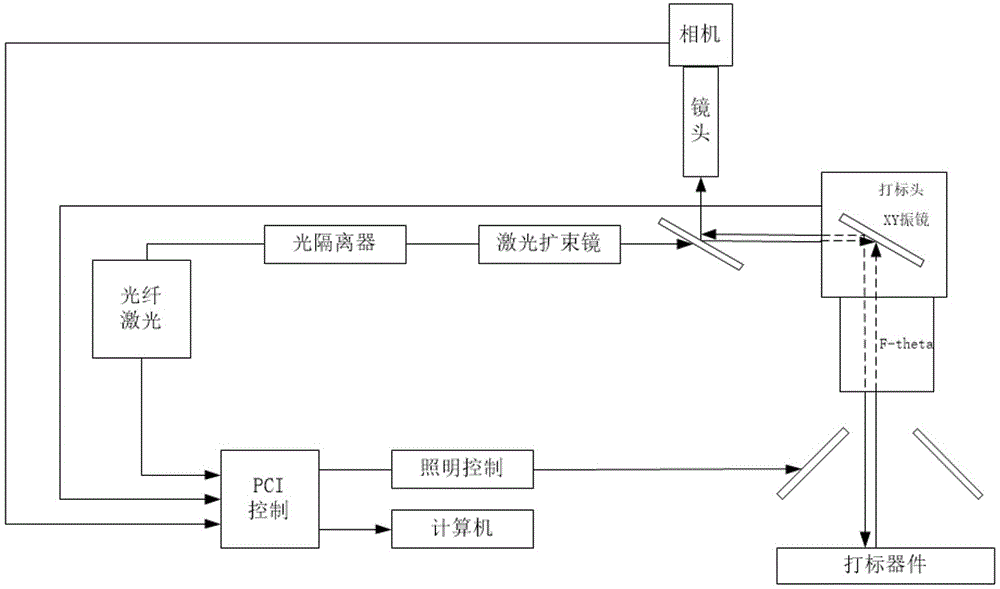
[0031] Such as figure 1 as shown, figure 1 It is a structural schematic diagram of a machine vision laser marking galvanometer scanning system proposed by the present invention.

[0032] refer to figure 1 , a machine vision laser marking galvanometer scanning system proposed by the present invention includes an image processing system, a laser galvanometer scanning system, and a motion control system, specifically including a light source, a lens, a CCD camera, an image acquisition card, image processing software, Fiber lasers, optical isolators, laser beam expanders, XY scanning galvanometers, F-theta lenses, monitors, communication / input / output units, three-dimensional adjustment brackets, etc. In the present invention, the marking device group is illuminated by an 890nm LED lighting lamp, and its reflected light enters the CCD camera for imaging after passing through the F-theta lens, XY galvanometer, 45-degree mirror, and camera lens, and the camera transmits the digital...


PUM


Abstract

The invention discloses a laser marking galvanometer scanning system based on machine vision. The laser marking galvanometer scanning system comprises an image processing system, a laser galvanometer scanning system and a motion control system and specifically comprises a light source, a camera lens, a CCD (Charge Coupled Device) camera, an image capture card, an image processing software, a fiber laser, an opto-isolator, a laser beam-expanding lens, an XY scanning galvanometer, an F-theta lens, a monitor, a communication / input output unit and a three-dimensional adjusting bracket. The laser marking galvanometer scanning system utilizes the machine vision to acquire the position of the workpiece from the view field of the camera, to finish the information capture and the signal conversion and to perform coordinate conversion and direction conversion on the marking document, so that the marking position on the subsequent workpiece is consistent with the position of the first workpiece. Meanwhile, the marking depth can be online measured and the information is supplied for the online feedback control on the laser marking. Compared with the traditional marking positioning, the laser marking galvanometer scanning system has the advantages that different fixtures need not be prepared for different workpieces, the purpose of positioning the workpiece is achieved by only training the machine vision for identifying different patterns, the real-time online detection for the marking quality is performed, the cost is lowered, the general automation is easily realized and the processing precision is further increased and ensured.

Description

technical field [0001] The invention relates to the technical field of machine vision, and relates to a machine vision laser marking vibrating mirror scanning system. Background technique [0002] Machine vision technology can rely on visual sensors to collect on-site images, analyze and process data, and then guide the machine to perform correct operations. It is a novel and practical science and technology. Through cameras and computers, machines can automatically measure targets, recognized function. [0003] Machine vision is widely used, from industrial detection to file processing, from remote sensing images to medical images, it can be applied to machine vision in almost any occasion where human vision plays a role. It will not feel tired, has high tracking speed and Resolution accuracy saves manpower in industrial production and improves product quality and production speed. [0004] Laser marking is a marking method that uses focused laser to generate high energy ...

Claims


Application Information

Patent Timeline
IPC IPC(8): G01C11/02
CPCG01C11/02
Inventor 陈志王春明黄禹谢拥军张强张冬冬唐舵
Owner 广东顺德华焯机械科技有限公司
Learn More