
A method for measuring the rotation angle of a rotating shaft to suppress the rotation error of the shafting inclination angle

A technology of inclination rotation and measurement method, which is applied in the measurement of the rotation angle of the rotating shaft and the field of high-precision rotation angle measurement of the rotating shaft, which can solve the problems affecting the accuracy of the rotation angle measurement of the rotating shaft 2, the rotation error, the processing error, etc.

Inactive Publication Date: 2017-12-26
CHANGCHUN INST OF OPTICS FINE MECHANICS & PHYSICS CHINESE ACAD OF SCI
View PDF5 Cites 0 Cited by
  • Summary
  • Abstract
  • Description
  • Claims
  • Application Information

AI Technical Summary

Problems solved by technology

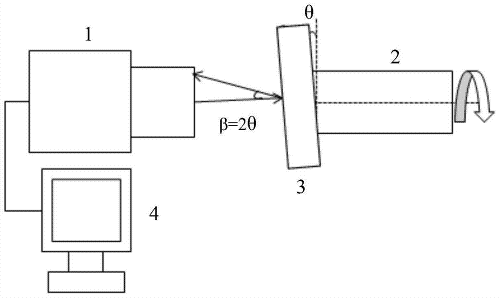
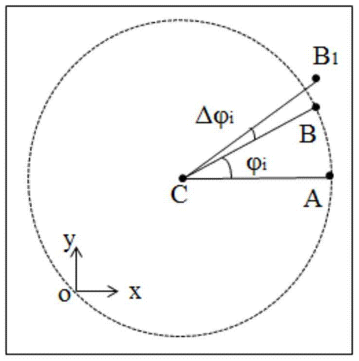
However, due to the machining error of the shaft, the installation error of the bearing, the clearance of the bearing itself, and the transmission force of the shaft during use, the swing occurs during the rotation of the shaft, which is professionally called the shaft system inclination rotation. The error, which causes the reflected light beam on the mirror 3 to swing, causes the light point image in the autocollimator 1 to deviate from the ideal circular track, and the deviation is twice the error of the axis tilt angle rotation, so that the end position changes from B point change to point B1, such as figure 2 As shown in the The inclination angle rotation error of the shaft system in different rotating mechanisms is different, generally ranging from a few arc seconds to tens of arc seconds
It can be seen that the inclination angle rotation error of the shaft system seriously affects the measurement accuracy of the rotation angle of the shaft 2

Method used


Image

  • A method for measuring the rotation angle of a rotating shaft to suppress the rotation error of the shafting inclination angle
  • A method for measuring the rotation angle of a rotating shaft to suppress the rotation error of the shafting inclination angle
  • A method for measuring the rotation angle of a rotating shaft to suppress the rotation error of the shafting inclination angle

Examples


Embodiment Construction

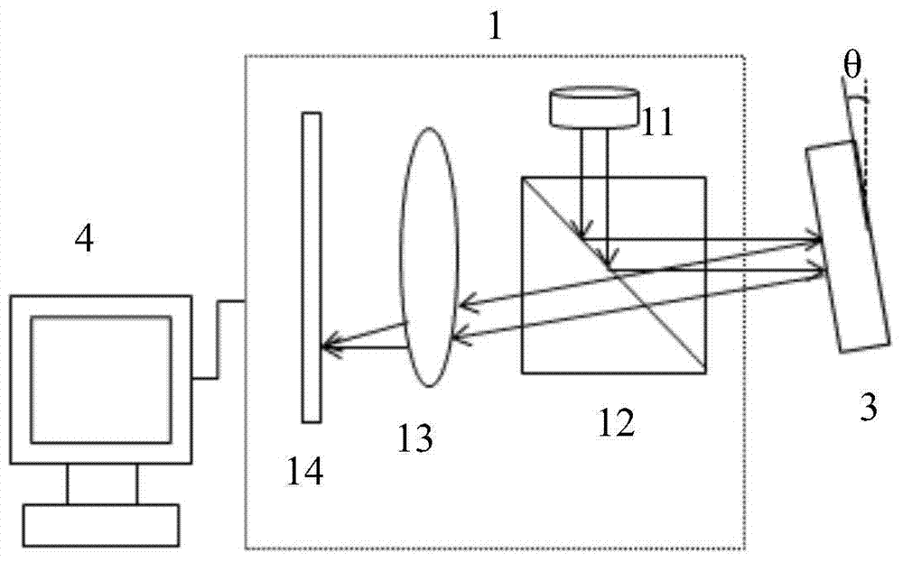
[0028] 1) Autocollimator 1 is Collapex AC300, a product of Xi'an Angke Spot Technology Co., Ltd., with an effective aperture of 32mm, a focal length of 300mm, and an imaging field of view of 50 arc minutes;

[0029] 2) The rotating shaft 2 is a hollow rotating shaft fixed with the worm wheel in the worm gear mechanism, driven by a servo motor, and the servo motor is connected with the computer 4;

[0030] 3) the computer 4 that links to each other with autocollimator 1 is the incidental equipment of autocollimator 1, and the program 1 that producer is given is installed on it, and the function of program 1 is: provide main interface on the display screen of computer 4, The position of the spot image is displayed on the main interface as a reticle, the center of the reticle is located at the centroid of the spot image, and the reticle moves synchronously with the position of the spot image; establish a Cartesian coordinate system and move along the display The horizontal direct...


PUM


Abstract

The invention belongs to the field of optical measurement, and is a method for measuring the rotation angle of a rotating shaft that can suppress the influence of the inclination angle rotation error of a shaft system. The measurement principle system of the present invention is shown in FIG. 1 , the rotating shaft 2 with the optical wedge 5 is placed between the autocollimator 1 and the reflector 3 . Due to the refraction effect of the optical wedge 5, the beam emitted by the autocollimator 1 is reflected by the reflector 3, forms a deflection angle β with the outgoing beam, returns to the autocollimator 1, and converges into a light point image; when the rotating shaft 2 and the light When the wedge 5 rotates integrally, the reflected light beam rotates around the axis of the rotating shaft 2, and the light spot image in the autocollimator 1 moves along a circular trajectory; the computer 4 records the centroid coordinates of the light spot image on the circumference, and fits the trajectory circle The coordinates of the center of the circle, and then specify the starting point A and the end point B on the circumference, and use the coordinate values ​​of A and B to calculate the corresponding circle center opening angle, which is the rotation angle of the rotation axis 2 to be measured from A to B. In the present invention, the rotation error of the inclination angle of the shaft system hardly affects the measurement accuracy of the rotation angle.

Description

technical field [0001] The invention belongs to the field of optical-mechanical detection, and is a high-precision method for measuring the rotation angle of a rotating shaft. The invention relates to a combination of an autocollimator, an optical wedge and a reflector, specifically a method for measuring the rotational angle of a rotating shaft that suppresses the rotational error of the inclination angle of the shaft system. Background technique [0002] According to the angle measurement principle of the autocollimator, it is easy to think of using figure 1 The optical path system shown is used to measure the rotation angle of the rotating shaft. Among them, 1 is an autocollimator, 2 is a rotating shaft, 3 is a mirror, and 4 is a computer; the mirror 3 is installed on the end face of the rotating shaft 2, and forms an angle θ with the end face of the rotating shaft 2; After the light beam is reflected by the reflector 3, it is deflected at an angle β=2θ relative to the ...

Claims


Application Information

Patent Timeline
Patent Type & Authority Patents(China)
IPC IPC(8): G01B11/26
CPCG01B11/26
Inventor 宣丽李文杰穆全全王少鑫曹召良李大禹杨程亮胡立发彭增辉刘永刚姚丽双徐焕宇王玉坤
Owner CHANGCHUN INST OF OPTICS FINE MECHANICS & PHYSICS CHINESE ACAD OF SCI
Learn More