Split exhaust for micro turbofan with rectifier

A turbofan engine, separate exhaust technology, applied in the direction of machine/engine, jet propulsion, etc., can solve the problems of thrust loss of micro turbofan engine, reduction of external airflow kinetic energy, radial dimension difference, etc. , reduce friction loss, light weight effect

Inactive Publication Date: 2017-04-19
NANJING UNIV OF AERONAUTICS & ASTRONAUTICS
View PDF7 Cites 0 Cited by
  • Summary
  • Abstract
  • Description
  • Claims
  • Application Information

AI Technical Summary

Problems solved by technology

[0005] For a micro turbofan engine that adopts a separate exhaust scheme for inner and outer connotations, the turbine guide needs to be assembled with the rear section of the intermediate casing and the inner nozzle. Due to the inherent radial dimension difference between the three, the installation surface is a radial annular step surface, located at At the outlet of the outer culvert, when the airflow ejected from the outer culvert passes through the large-sized back step, a vortex will be generated, which will cause serious viscosity loss, reduce the kinetic energy of the outer culvert airflow, and further cause the thrust loss of the micro turbofan engine

Method used


Image

  • Split exhaust for micro turbofan with rectifier
  • Split exhaust for micro turbofan with rectifier
  • Split exhaust for micro turbofan with rectifier

Examples


Embodiment Construction

[0026] Below in conjunction with accompanying drawing, technical scheme of the present invention is described in further detail:

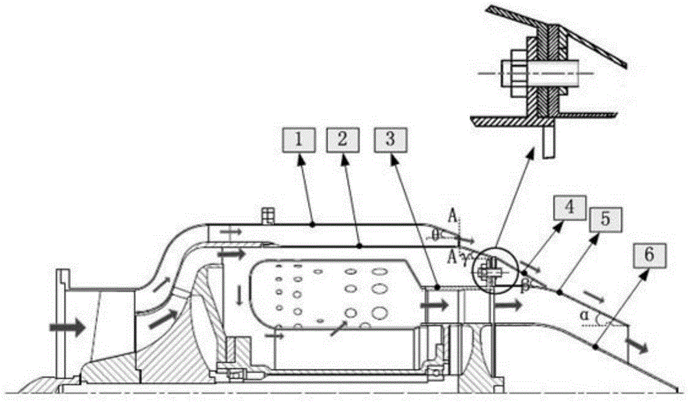
[0027] Such as figure 1 and image 3 As shown, the present invention discloses a separate exhaust device for a micro-turbofan engine with a rectifier, which is located at the exhaust outlet of the turbofan engine and includes an outer casing, an intermediate casing, a turbine guide casing, a rectifier, Inner nozzle and center cone;

[0028] The outer casing, the intermediate casing, the turbine guide casing, the inner nozzle, the rectifier, and the center cone are connected in sequence, wherein the tail of the turbine guide casing is provided with a first flange mounting edge; the intermediate casing The tail of the box is provided with a second flange installation edge; the front end of the internal nozzle is provided with a third flange installation edge;

[0029] Such as figure 2 As shown, the rectifier is in the shape of a conical surface ...


PUM


Abstract

The invention discloses a miniature turbofan engine separate exhausting device with a rectifier. The miniature turbofan engine separate exhausting device is located in the position of an exhausting outlet of a miniature turbofan engine and comprises an outer case, a turbine guider case, the rectifier, an intermediate case, an inner spray pipe and a center cone which are sequentially connected. The difference value between the shrinkage angle of the rectifier and the shrinkage angle of the inner spray pipe and the difference value between the shrinkage angle of the rectifier and the shrinkage angle of the rear section of the outer case both range from -5 degrees to 5 degrees. By the adoption of the miniature turbofan engine separate exhausting device, friction loss and viscosity loss caused in the exhausting process of the miniature turbofan engine can be greatly reduced; and in addition, the problem that a thread is difficultly machined on high-temperature alloy is solved, connection is convenient, and the structure is simple and feasible.

Description

technical field [0001] The invention relates to the field of micro turbofan engines, in particular to a separate exhaust device for micro turbofan engines with a rectifier. Background technique [0002] The micro-turbojet engine has the advantages of light weight, high power, high energy storage density, high power-to-weight ratio and thrust-to-weight ratio, and is currently widely used in small or micro aircraft such as small drones, small missiles, and jet model aircraft. However, its fuel consumption rate is high, and the thrust still cannot meet the power requirements of aircraft such as micro cruise bombs that need to carry more ammunition. Reducing fuel consumption is of great significance to small engines. For small UAVs, it means that it can carry more airborne equipment or a longer range; for small missiles, it means that it can increase the payload ratio. The weight ratio of the whole bomb, or increase the range of the missile. The development of micro turbofan e...

Claims


Application Information

Patent Timeline
Patent Type & Authority Patents(China)
IPC IPC(8): F02K3/00
Inventor 王进春黄慧慧黄国平胡晓辰
Owner NANJING UNIV OF AERONAUTICS & ASTRONAUTICS
Why Eureka
Try Eureka