
A remote intelligent control system for electric vehicle charging piles

A remote intelligent control and electric vehicle technology, applied in the field of electric vehicle charging and Internet of Things, can solve the problems of no electricity, high cost, and deterioration of reliability and average bandwidth of the car, so as to save cable and labor costs, save work efficiency, The effect of simple installation and operation

Active Publication Date: 2018-07-06
罗昆
View PDF5 Cites 0 Cited by
  • Summary
  • Abstract
  • Description
  • Claims
  • Application Information

AI Technical Summary

Problems solved by technology

The mobile data service of mobile operators needs to connect electric vehicle charging piles, an internal device of the power grid, to the mobile data network of mobile operators, and it is necessary to pay expensive monthly and annual fees. As the number of charging piles increases, the cost will increase. At the same time, data security and network reliability are restricted by mobile operators, which is not conducive to the safe operation of equipment; secondly, the mobile access bandwidth of mobile operators is a shared bandwidth, when a large number of devices access , the reliability of its access and the average bandwidth of each user will deteriorate, which is not conducive to the intensive access of charging pile groups and the transmission of large amounts of data
[0006] As the country vigorously supports the electric vehicle industry in terms of policy, electric vehicles and battery cars are becoming more and more common, followed by charging problems. What if the car has no electricity? Are there charging stations there? Is the charging pile free? How far is the distance from here, etc., the existing technology cannot make the owners of electric vehicles solve the above problems conveniently

Method used


Image

  • A remote intelligent control system for electric vehicle charging piles
  • A remote intelligent control system for electric vehicle charging piles

Examples


Embodiment Construction

[0021] Embodiments of the present invention are described in detail below, examples of which are shown in the drawings, wherein the same or similar reference numerals denote the same or similar elements or elements having the same or similar functions throughout. The embodiments described below by referring to the figures are exemplary only for explaining the present invention and should not be construed as limiting the present invention.

[0022] Below in conjunction with accompanying drawing, technical scheme of the present invention is described in further detail:

[0023] It should be emphasized that what the present invention intends to protect is the specific system architecture structure and various communication line connection and erection methods, and does not involve the specific content of computer software. The invention focuses on specific hardware device settings and communication line construction. Through the system architecture disclosed in the present invent...


PUM


Abstract

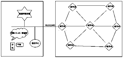
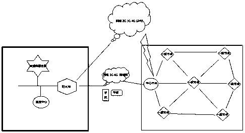
The invention discloses a remote intelligent control system for electric vehicle charging piles, which includes front-end monitoring data acquisition equipment, ZigBee transmission equipment, a central monitoring system and mobile terminal equipment; the front-end monitoring data acquisition equipment includes power data acquisition equipment, user information acquisition equipment and human-computer interaction equipment; the ZigBee transmission equipment establishes a wireless network by itself, and establishes a two-way communication link between the front-end monitoring data acquisition equipment, the central monitoring system and the mobile terminal; the central monitoring system includes a server unit. The control system disclosed in the present invention enables the electric vehicle driver to accurately and conveniently know the relevant information such as the location of the nearest charging pile, the quantity that can be charged, the voltage and current status, the charging standard, etc., which is convenient and quick, saves work efficiency, and is beneficial to the charging of the electric vehicle Large-area and large-scale promotion of piles. Save costs, save laying a large number of cables and labor costs.

Description

technical field [0001] The invention discloses a remote intelligent control system for an electric vehicle charging pile, and relates to the technical fields of electric vehicle charging and the Internet of Things. Background technique [0002] Electric vehicles are a hot direction in the development of automobiles. The function of the charging pile is similar to that of the fuel dispenser in the gas station. It can be fixed on the ground or on the wall, and installed in public buildings (public buildings, shopping malls, public parking lots, etc.) and residential area parking lots or charging stations. Charge all models of electric vehicles. The input end of the charging pile is directly connected to the AC grid, and the output end is equipped with a charging plug for charging the electric vehicle. Charging piles generally provide two charging methods: conventional charging and fast charging. People can use a specific charging card to swipe the card on the human-computer ...

Claims


Application Information

Patent Timeline
Patent Type & Authority Patents(China)
IPC IPC(8): H04L29/08H04W84/18B60L11/18
CPCH04L67/025H04W84/18B60L53/31Y04S30/12Y02T10/70Y02T90/167Y02T90/12Y02T10/7072
Inventor 罗昆
Owner 罗昆
Learn More