
LED module light source

A technology of LED modules and LED chips, which is applied in the direction of electric light sources, semiconductor devices, lighting and heating equipment, etc., can solve problems such as fracture, low mechanical strength of bonding wires, internal stress damage of packaging colloid, etc., and achieve the elimination of internal stress, Excellent light extraction effect, avoiding shear stress and elastic modulus effect

Active Publication Date: 2016-03-16
APT ELECTRONICS
View PDF14 Cites 0 Cited by
  • Summary
  • Abstract
  • Description
  • Claims
  • Application Information

AI Technical Summary

Problems solved by technology

[0007] The purpose of the present invention is to provide a LED module light source, which can effectively solve the problem of low mechanical strength of the bonding wire, which is easily damaged by external impact force and internal stress of the packaging colloid, and thus breaks, and has a long life and reliability. high sex

Method used


Image

  • LED module light source
  • LED module light source
  • LED module light source

Examples


Embodiment 1

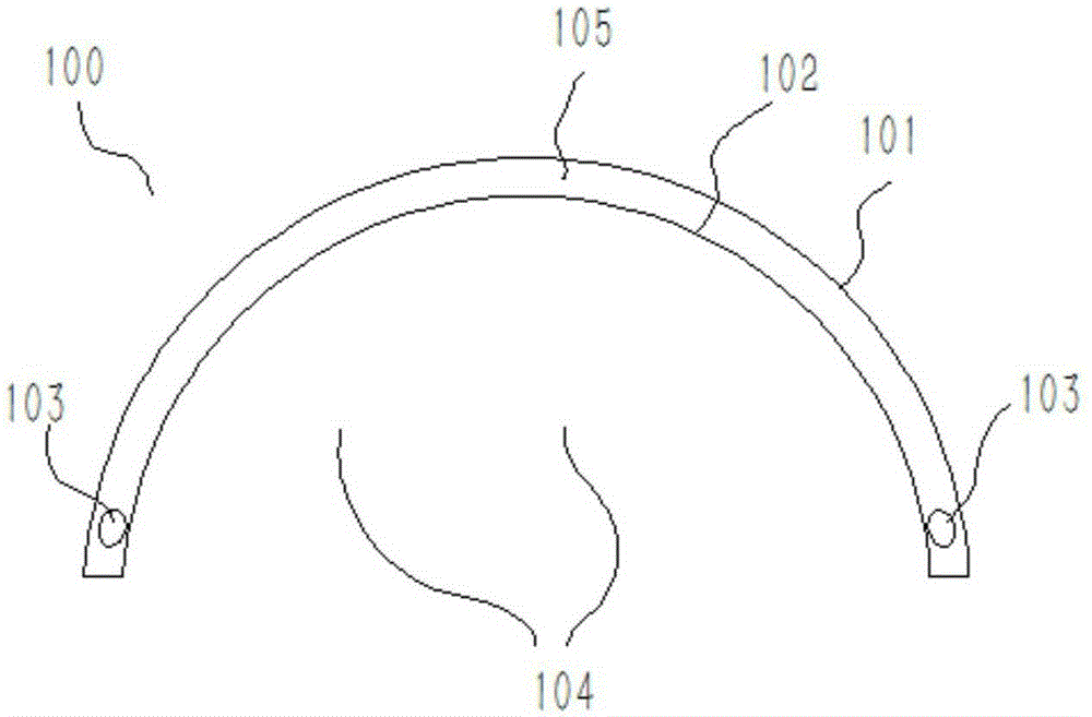
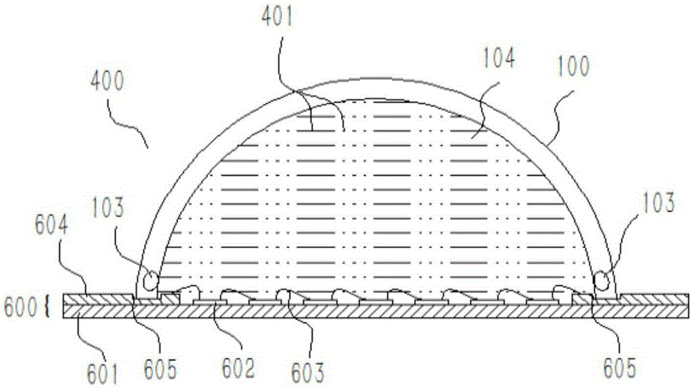
[0040] Such as Figure 2-4 As shown, the lens 100 is installed on the base 600 , and the opening edge of the lens 100 is butted and glued to the installation groove 605 of the base 600 .

[0041] The lens 100 includes a filling cavity 104 , the filling cavity 104 forms a closed space with the substrate 601 , and the first filler 401 is filled in the closed space. The first filler 401 is a colorless, transparent non-solid substance, and is non-conductive, thereby avoiding the shear stress and elastic modulus in the traditional solid potting glue, and completely eliminating the thermal loss caused by different packaging materials. The combination acts on the internal stress of the bonding wire, which greatly improves the long-term reliability of the bonding wire, thereby reducing the harsh requirements of the reliability of the package on the material system and packaging technology. The LED chip 602 and the bonding wire 603 are located in the enclosed space.

[0042] The lens...

Embodiment 2

[0053] The technical scheme of this embodiment and embodiment 1 is basically the same, and its difference mainly lies in:

[0054] The structure of the lens 200 of this embodiment is different from that of the lens 100 in Embodiment 1, wherein, as Figure 5 As shown, the inner surface 202 and the outer surface 201 of the lens body 205 in this embodiment are curved surfaces, and its cross-sectional view is wavy.

Embodiment 3

[0056] The technical scheme of this embodiment and embodiment 1 is basically the same, and its difference mainly lies in:

[0057] The structure of the lens 300 in this embodiment is different from that of the lens 100 in Embodiment 1 and the lens 200 in Embodiment 2, wherein, as Figure 6 As shown, the inner surface 302 of the lens body 305 in this embodiment is a curved surface, specifically as Figure 6 It is a curved surface, and the outer surface 301 is a serrated plane.

[0058] It should be noted that the structure of the lens of the present invention includes but not limited to the three structures described in Embodiments 1, 2 and 3.


PUM


Abstract

The invention discloses an LED module light source which comprises a lens arranged on a substrate. The lens comprises a filling cavity, a closed space is formed by the filling cavity and the substrate and filled with a first filling agent, and the first filling agent is a colorless and transparent non-solid substance free of electric conductivity. The lens further comprises multiple energy absorption cavities filled with a second filling agent which is colorless and transparent gas. LED chips and bonding wires are located in the closed space. By the adoption of the LED module light source, the problem that bonding wires are likely to be damaged by external impact force and internal stress of a packaging rubber body so as to be broken due to the low mechanical strength can be solved effectively, and the LED module light source is long in service life and high in reliability.

Description

technical field [0001] The invention relates to the technical field of LEDs, in particular to an LED module light source. Background technique [0002] LED integrated module packaging light source is very popular in the fields of home lighting, commercial lighting, venues, and industrial and mining lighting. Integrated packaging has always played an important part of the LED lighting device market due to its excellent light quality, excellent light efficiency performance, good optical design latitude and excellent cost performance. [0003] The general form of the LED integrated module light source is: metal, ceramic or other materials are used as the substrate, and a front-mounted or flip-chip LED chip is arranged on it. The chip area is surrounded by walls, and fluorescent conversion materials are coated in it. [0004] Among them, the integrated module light source using flip-chip LED chips only occupies a small share in the market due to the high threshold of flip-chip ...

Claims


Application Information

Patent Timeline
Patent Type & Authority Applications(China)
IPC IPC(8): F21S2/00H01L33/56H01L33/58
CPCH01L33/56H01L33/58F21S2/005H01L2224/48137
Inventor 刘桂良万垂铭文家祥姜志荣姚述光曾照明肖国伟
Owner APT ELECTRONICS
Learn More