
A passive hydraulic braking system

A hydraulic brake and hydraulic brake technology, applied in fluid pressure actuation system testing, fluid pressure actuation system safety, brake actuators, etc., can solve problems such as short safe operation time, increased equipment maintenance, and many valve groups , to achieve the effect of prolonging the safe running time, reducing the maintenance difficulty and reducing the cost

Active Publication Date: 2018-06-26
XIANGTAN HENGXIN IND
View PDF7 Cites 0 Cited by
  • Summary
  • Abstract
  • Description
  • Claims
  • Application Information

AI Technical Summary

Problems solved by technology

[0002] The braking system of traditional rail transportation equipment is to drive the pump to rotate directly through the wheels, and then brake the equipment through a series of valve groups. Too many valve groups are used, resulting in more leakage points, which increases the difficulty and cost of equipment maintenance. Correspondingly higher
And there is no supplementary pressure measure, resulting in a shorter safe running time of the system

Method used


Image

  • A passive hydraulic braking system
  • A passive hydraulic braking system
  • A passive hydraulic braking system

Examples


Embodiment Construction

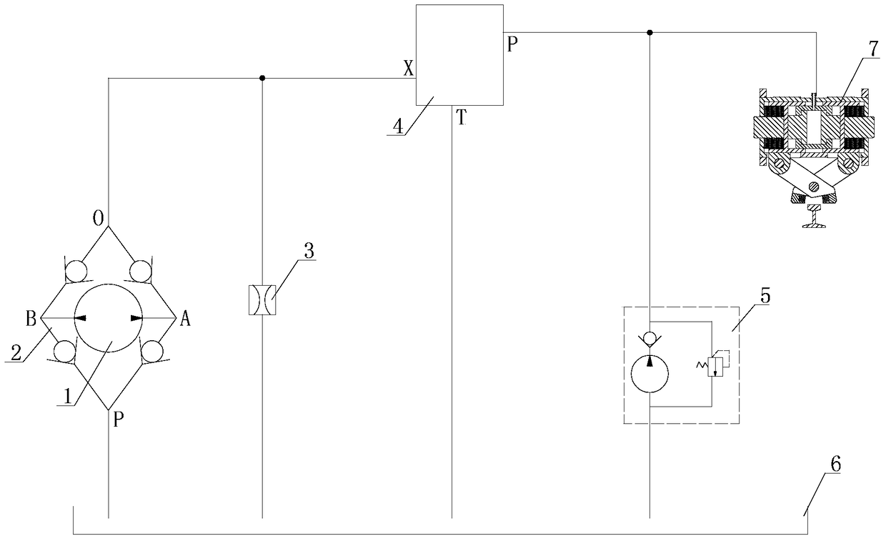
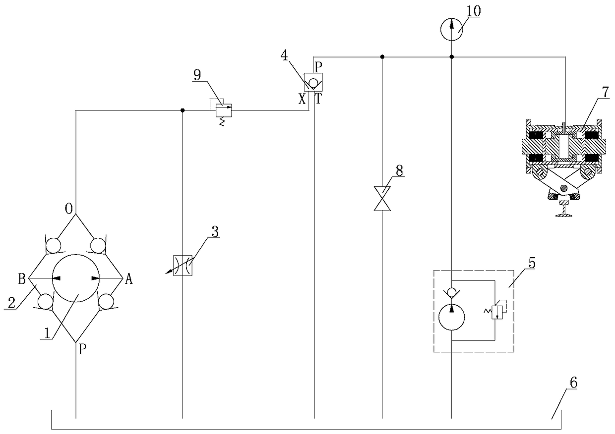
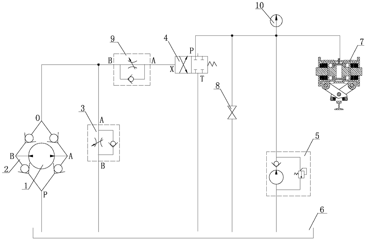
[0015] Such as figure 1 , figure 2 , image 3 As shown, a passive hydraulic braking system includes an oil pump 1; a hydraulic bridge 2; a flow control device 3; a pressure relief device 4 with a pressure maintaining function; a hydraulic brake 7; a hand pump 5; a fuel tank 6;

[0016] The oil inlet and outlet of the oil pump 1 are connected to ports A and B of the hydraulic bridge 2 through oil pipes, the oil inlet P of the hydraulic bridge 2 is connected to the oil tank 6 through the oil pipe, and the oil outlet O of the hydraulic bridge 2 is connected to the oil tank 6 through the flow control device 3 , The oil outlet O of the hydraulic bridge 2 is connected to the control oil port X of the pressure relief device 4 with the pressure maintaining function, and the oil discharge port T of the pressure relief device 4 with the pressure maintaining function is connected to the fuel tank 6, and the pressure relief device with the pressure maintaining function The oil inlet P ...


PUM


Abstract

The invention discloses a passive hydraulic braking system which comprises an oil pump, a hydraulic bridge, a flow control device, a pressure relief device with the pressure maintaining function, a hydraulic brake, a manual pump and an oil tank. The system has the following technical effects that passive braking can be achieved, and in other words, braking can be achieved without dependence on additionally-provided external power such as a motor; due to the fact that adopted control valve packs are few, leakage of hydraulic oil is relatively small, the maintenance difficulty is further lowered, and cost is effectively reduced; and the reliable pressure supplementing measures are set, so that the safety operation time of the system is prolonged.

Description

technical field [0001] The invention relates to a hydraulic braking system. Background technique [0002] The braking system of traditional rail transportation equipment is to drive the pump to rotate directly through the wheels, and then brake the equipment through a series of valve groups. Too many valve groups are used, resulting in more leakage points, which increases the difficulty and cost of equipment maintenance. also correspondingly higher. And there is no supplementary pressure measure, resulting in a shorter safe running time of the system. Contents of the invention [0003] The object of the present invention is to provide a passive hydraulic braking system. [0004] The technical solution of the present invention is a passive hydraulic braking system, including an oil pump, a hydraulic bridge, a flow control device, a pressure relief device with a pressure maintaining function, a hydraulic brake, a manual pump, and an oil tank; [0005] The inlet and outlet...

Claims


Application Information

Patent Timeline
Patent Type & Authority Patents(China)
IPC IPC(8): F16D65/14F15B20/00F15B19/00F16D121/02F16D125/02
Inventor 肖公平肖连平陈林
Owner XIANGTAN HENGXIN IND
Learn More