
Power source system

A power supply system and battery technology, applied in control systems, electric vehicles, electrical components, etc., can solve the problem of increasing the number of components

Inactive Publication Date: 2016-03-09
DENSO CORP
View PDF7 Cites 2 Cited by
  • Summary
  • Abstract
  • Description
  • Claims
  • Application Information

AI Technical Summary

Problems solved by technology

[0004] However, as the power supply relay and the reverse connection protection relay are provided separately, the number of parts increases

Method used


Image

  • Power source system
  • Power source system
  • Power source system

Examples


Embodiment 1

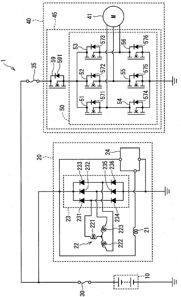
[0014] Such as figure 1 As shown, a power supply system 1 according to an embodiment of the present disclosure is a vehicle power supply system including a battery 10 , an alternator 20 as a generator, a first fuse 30 , a second fuse 35 and a driving device 40 .

[0015] The battery 10 is an auxiliary battery connected to an alternator 20, a drive device 40, and vehicle auxiliary equipment such as a water or oil pump and power window equipment.

[0016] The alternator 20 is a three-phase alternator driven by the driving force of an engine (not shown), and serves as a power source for a stator or the like (not shown), or as a charger for charging the battery 10 . For example, the alternator 20 includes a rotor coil 21 , a stator coil 22 , a rectifier circuit 23 and a regulator 24 .

[0017] The rotor coil 21 is provided on a rotor that is rotated by the driving force of the engine, and generates magnetic flux by the flow of an exciting current. One end of the rotor coil 21 is...


PUM


Abstract

Disclosed is a power source system which provides an electrical generator (20) including a rectifying circuit (23) configured by one or more rectifying diodes (231-236) for allowing electric conduction from a ground side to a battery side; a fuse (30) arranged between the electrical generator and a battery (10); and a driving apparatus (40) including a circuit (45) configured by one or more semiconductor elements (51-56,59) having one or more parasitic diodes (571-576) for allowing electrical conduction from the ground side to the battery side, and a load (41). The number of parasitic diodes to be connected in series between a ground and the fuse in the driving apparatus is larger than the number of rectifying diodes to be connected in series between the ground and the battery side in the electrical generator. In addition, the circuit switches electrical conduction in the load.

Description

technical field [0001] The present disclosure relates to a power supply system. Background technique [0002] As is well known, in a motor drive device, a power relay is provided between a battery and an inverter. For example, Japanese Patent Application Publication No. 2014-45578 discloses configuring a power relay provided between a battery and an inverter through a MOSFET. [0003] Japanese Patent Application Publication No. 2014-45578 discloses that a power relay is added between the battery and the inverter, and a reverse connection protection relay is provided so that the parasitic diode is in the opposite direction to the power relay. Therefore, when the battery is wrongly connected in the reverse direction, the motor drive device can be protected. [0004] However, as the power supply relay and the reverse connection protection relay are provided separately, the number of components increases. Contents of the invention [0005] An object of the present disclosur...

Claims


Application Information

Patent Timeline
Patent Type & Authority Applications(China)
IPC IPC(8): B62D5/04B60R16/02H02H7/06H02H7/122
CPCH02H7/1222H02M1/10H02M7/48H02P29/0241H02P27/06Y02T10/70B60L50/51H02P29/024
Inventor 山本敏久株根秀树
Owner DENSO CORP
Learn More