
Stub bar punching device

A technology of material head and punching die, which is applied in the field of material head punching device, can solve the problems of low production efficiency and achieve the effects of high production efficiency, good product consistency and high practical value

Active Publication Date: 2016-03-09
宁波拓普电器有限公司
View PDF6 Cites 7 Cited by
  • Summary
  • Abstract
  • Description
  • Claims
  • Application Information

AI Technical Summary

Problems solved by technology

[0003] The present invention solves the problem of low production efficiency in the prior art that single multiple punching is used for the separation of whole mold parts and workpieces, and provides a kind of single punching that can complete the separation of multiple workpieces, with high production efficiency and product consistency Good head punching device

Method used


Image

  • Stub bar punching device
  • Stub bar punching device
  • Stub bar punching device

Examples


Embodiment 1

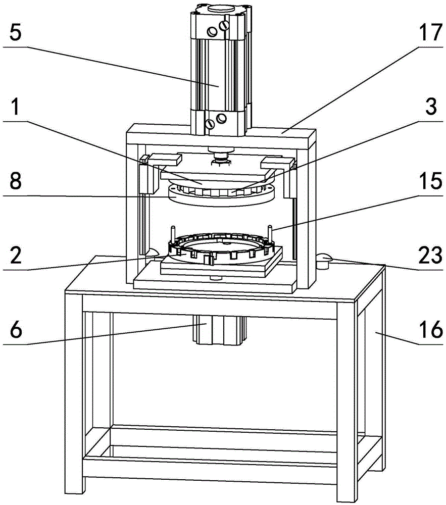
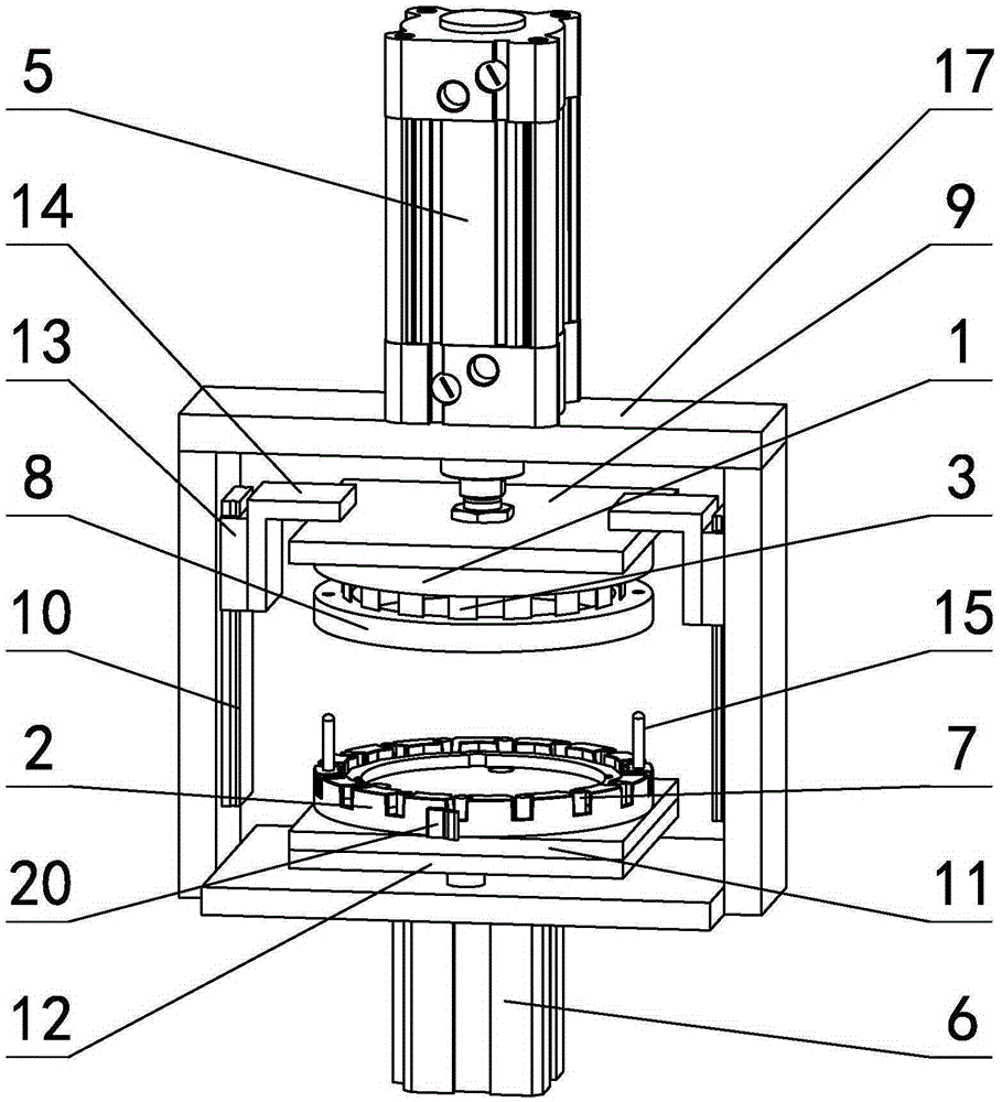
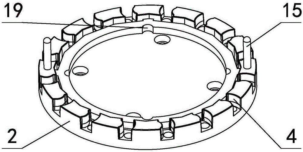
[0027] in such as figure 1 figure 2 In the shown embodiment 1, a kind of head punching device comprises a frame composed of a base 16 and a rectangular frame 17 arranged on the base, the frame is provided with an upper mold base 1 and The lower mold base 2, the upper mold base is circular, and the bottom surface of the upper mold base is provided with 16 punching dies 3 arranged in a ring, and the punching dies are cutting knives (see Figure 4 ), the cutting knives are evenly distributed along the circumferential direction of the circular upper die base, the head of the cutter is provided with a cutting edge on the side close to the workpiece groove, and the cutting edge line of the cutting knife is inclined relative to the bottom surface of the upper die base. The inclination angle of the edge line relative to the bottom surface of the upper die base is 25 degrees. The lower side of the upper mold base is provided with a circular workpiece pressure plate 8, the workpiece ...


PUM


Abstract

The invention discloses a stub bar punching device. A rack is provided with an upper die seat and a lower die seat. The bottom face of the upper die seat is provided with multiple punching dies annularly arranged. The top face of the lower die seat is provided with workpiece grooves corresponding to the punching dies. The portion, above the upper die seat, of the rack is provided with a punching air cylinder connected with the upper die seat. The portion, below the lower die seat, of the rack is provided with an ejection air cylinder. The ejection air cylinder is connected with ejector rods arranged in the workpiece grooves. By means of the stub bar punching device, the problems that the manner in which a single workpiece is punched multiple times is adopted and production efficiency is very low in the prior art are solved effectively; and multiple workpieces can be separated through one-time punching, production efficiency is high, the uniformity of products is good, and the stub bar punching device has very high practical value.

Description

technical field [0001] The invention relates to the technical field of mechanical processing, in particular to a chip punching device capable of cutting multiple plastic or elastic body workpieces at one time. Background technique [0002] In the prior art, a single plastic or elastomer workpiece is cut and separated from the whole mold part, and most of them adopt a single multiple punching processing method, that is, each time the next workpiece is punched from the whole mold part, and the whole mold part is integrally connected. Many workpieces need to go through multiple punching to complete. The production efficiency of this punching method is very low, and the punching surface of each workpiece has certain differences, and the consistency of the workpieces is poor, which affects the quality of the workpieces. The publication date is September 26, 2012, and the patent document with the publication number CN202447479U discloses a cantilever vibrator head cutting device,...

Claims


Application Information

Patent Timeline
Patent Type & Authority Applications(China)
IPC IPC(8): B26F1/38B26F1/44B26D7/18B26D7/01
Inventor 叶志伟熊鑫田和平
Owner 宁波拓普电器有限公司
Learn More