
Forced cooling of chassis and method thereof

A technology of forced cooling and chassis, applied in the field of forced cooling chassis and forced cooling, can solve the problems of easy burning and deformation, easy burning, shortening the service life of steel ingot chassis, etc., and achieve the effect of reducing cost and simple process

Active Publication Date: 2017-12-12
MCC CAPITAL ENGINEERING & RESEARCH
View PDF5 Cites 0 Cited by
  • Summary
  • Abstract
  • Description
  • Claims
  • Application Information

AI Technical Summary

Problems solved by technology

Steel ingot is used as an indispensable billet preparation scheme for thick plate production. During the casting process, the middle and lower parts of the ingot mold and the high-temperature area of ​​the chassis are easy to be burned, resulting in local melting loss of the ingot mold; especially around the injection hole of the steel ingot chassis. The high temperature part is easy to burn and deform due to contact with high temperature molten steel, thus shortening the service life of the steel ingot chassis

Method used


Image

  • Forced cooling of chassis and method thereof
  • Forced cooling of chassis and method thereof
  • Forced cooling of chassis and method thereof

Examples


Embodiment Construction

[0058] The above and other technical features and advantages of the present invention will be clearly and completely described below in conjunction with the accompanying drawings. Apparently, the described embodiments are only some of the embodiments of the present invention, not all of them.

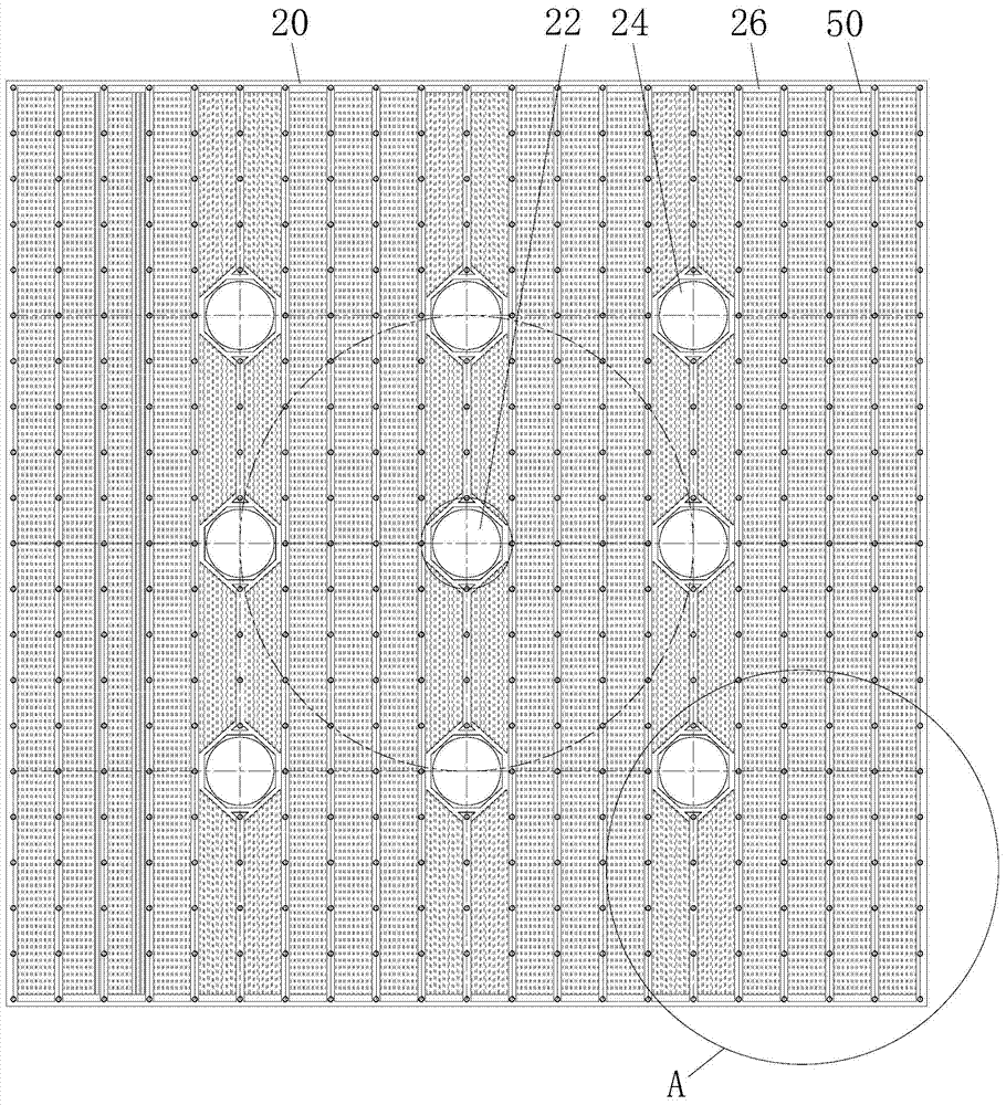
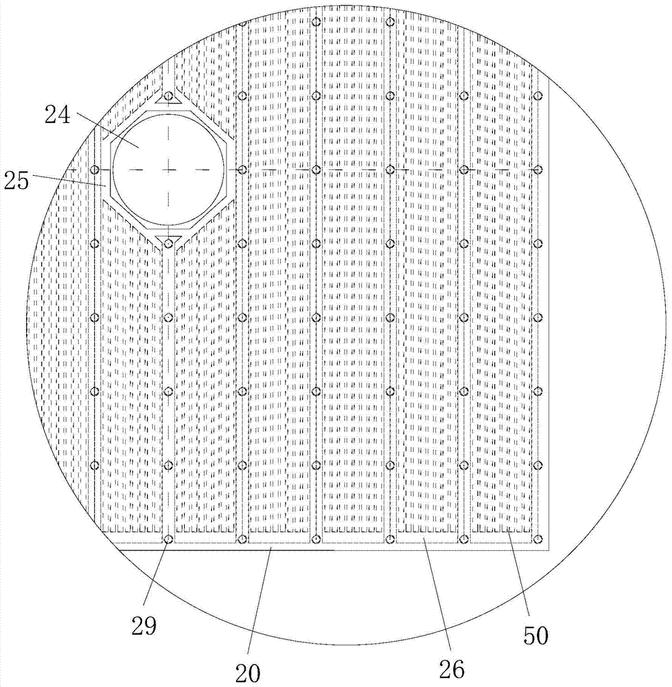
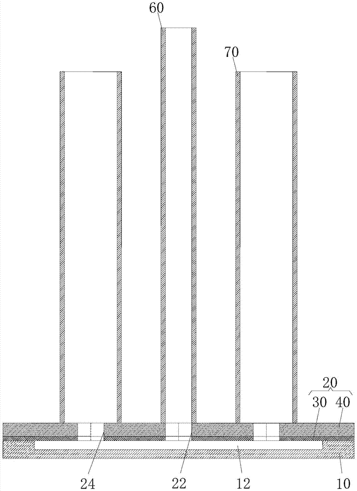
[0059] see Figure 1 to Figure 3 As shown, a forced cooling chassis of the present invention includes a bottom plate 10 and a composite plate 20 stacked on the upper surface of the bottom plate 10 . A pouring hole 22 and at least two drain holes 24 arranged around the pouring hole 22 are provided on the composite plate 20, the pouring hole 22 and the drain hole 24 are separately arranged, and the pouring hole 22 and the drain hole 24 all pass through the composite plate vertically 20. At least two molten steel grooves 12 extending from the pouring holes 22 to the drainage holes 24 are provided on the upper surface of the bottom plate 10, and the pouring holes 22 and the drainage holes ...


PUM


Abstract

The invention provides a forced cooling chassis and a method thereof. The forced cooling chassis comprises a base plate and a combination plate overlaid on the upper surface of the base plate; the combination plate is provided with a pouring hole and at least two drainage holes formed around the pouring hole, and the pouring hole and the drainage holes are arranged in a separated manner and penetrate the combination plate in the vertical direction; at least two molten steel grooves extending from the pouring hole to all drainage holes are formed in the upper surface of the base plate, and the pouring hole and the drainage holes are communicated through the molten steel grooves corresponding to the drainage holes and form a molten steel injection channel; and the combination plate comprises a back plate and a working plate overlaid and fixed to the upper surface of the back plate, the lower surface of the working plate and the upper surface of the back plate are attached in a sealing manner, a plurality of transversely-extending cooling through grooves for circulating cooling water are formed in the lower surface of the working plate or the upper surface of the back plate, and the cooling through grooves and the injection channels are not communicated. By means of the forced cooling chassis and the method, the cooling intensity of a steel ingot can be improved.

Description

technical field [0001] The invention relates to the technical field of casting equipment, in particular to a forced cooling chassis for cooling large steel ingots and a corresponding forced cooling method. Background technique [0002] The current foundry industry usually uses metal ingot mold equipment for the crystallization of liquid metal. The conventional ingot mold body is a hollow structure. During the cooling process of liquid metal, a large amount of heat released by the cooling and solidification of the metal is absorbed by the ingot mold body. High, especially the parts that are in contact with the liquid metal are prone to adhesion, scratches, and pieces. On the one hand, it seriously affects the service life of the ingot mold, and on the other hand, it also affects the quality of the solidified product, which affects the surface finish of the casting. [0003] With the demand for large-scale and diversified steel in practical applications, the concept of thick ...

Claims


Application Information

Patent Timeline
Patent Type & Authority Patents(China)
IPC IPC(8): B22D7/12
CPCB22D7/12
Inventor 耿明山刘艳曹建宁李耀军
Owner MCC CAPITAL ENGINEERING & RESEARCH
Learn More