
Solid waste treatment device and method

A solid waste and treatment device technology, applied in solid separation, chemical instruments and methods, magnetic separation, etc., can solve the problems of easy air pollution, large investment and high cost of incineration, and reduce labor intensity and resource area. , the effect of small footprint

Active Publication Date: 2016-03-09
NANJING JIARONG RENEWABLE MATERIALS RECOVERY CO LTD
View PDF11 Cites 2 Cited by
  • Summary
  • Abstract
  • Description
  • Claims
  • Application Information

AI Technical Summary

Problems solved by technology

[0002] At present, urban solid waste treatment methods are mainly landfill, incineration and recycling. Among them, landfill will occupy a large area of ​​land, waste land resources, and require a large investment. If the landfill seepage is not handled well, It may also pollute groundwater sources and easily cause secondary pollution to the environment
The incineration method is a high-temperature treatment technology, that is, a certain amount of excess air and the organic matter to be treated are oxidized and burned in the incinerator. The harmful substances in the waste are oxidized and pyrolyzed at high temperature and destroyed. The incineration method requires a large investment. , The capital occupation period is long, the combustion requires a large amount of fuel, the operating cost is high, the soot generated by the combustion is large, the composition is complex, the flue gas treatment is difficult, and it is easy to pollute the atmosphere
[0003] Existing methods for recycling solid waste have complex processes, require more mechanical equipment, cannot classify the substances in the waste, and are costly

Method used


Image

  • Solid waste treatment device and method
  • Solid waste treatment device and method
  • Solid waste treatment device and method

Examples


Embodiment

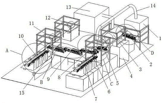
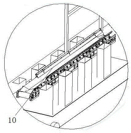
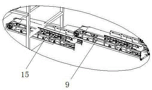
[0030] Such as figure 1 , 2 , 3, 4 and 5 shown in a solid waste treatment device, including sequentially arranged silo 1, the first conveying equipment 2, trommel 3, magnetic separator 5, eddy current magnetic separator and electromagnetic separator 12. The eddy current magnetic separator includes a first stage eddy current magnetic separator 8 and a second stage eddy current magnetic separator 8 . Sorting is carried out by a two-stage eddy current magnetic separator, and the scrap iron with impurities, that is, slag iron, is sorted out. The discharge port of the silo 1 is connected with the feed port of the trommel 3 through the first conveying equipment 2; it also includes an air magnetic separator 6, a gravity air separator 11 and an eddy current separator 15, the wind magnetic separator 11 and the eddy current separator 15. The magnetic separator 6 is connected with the magnetic separator 5 . A vibrating feeder is provided below the silo 1, and the vibrating feeder can ...


PUM

PropertyMeasurementUnit
Lengthaaaaaaaaaa

Abstract

The invention belongs to the technical field of solid waste treatment and particularly provides a solid waste treatment device. The solid waste treatment device comprises a bin, first conveying equipment, a drum screen, a magnetic separator, a vortex type magnetic separator and an electromagnetic separator, wherein the bin, the first conveying equipment, the drum screen, the magnetic separator, the vortex type magnetic separator and the electromagnetic separator are arranged in sequence. A discharge outlet of the bin is connected with a feed inlet of the drum screen through the first conveying equipment. The solid waste treatment device further comprises a wind magnetic separator, a gravity wind separator and an eddy current separator, wherein the wind magnetic separator is connected with the magnetic separator. The solid waste treatment device is reasonable in structure, small in occupied area and good in separation effect. The invention further provides a solid waste treatment method using the solid waste treatment device. By the adoption of the solid waste treatment method, the labor intensity of workers is relieved, the separation effect is good, economization and environmental friendliness are achieved, and the utilization rate of separated solid waste is high.

Description

technical field [0001] The invention belongs to the technical field of solid waste treatment, and in particular relates to a solid waste treatment device and a method thereof. Background technique [0002] At present, urban solid waste treatment methods are mainly landfill, incineration and recycling. Among them, landfill will occupy a large area of ​​land, waste land resources, and require a large investment. If the landfill seepage is not handled well, It may also pollute groundwater sources and easily cause secondary pollution to the environment. The incineration method is a high-temperature treatment technology, that is, a certain amount of excess air and the organic matter to be treated are oxidized and burned in the incinerator. The harmful substances in the waste are oxidized and pyrolyzed at high temperature and destroyed. The incineration method requires a large investment. , The capital occupation period is long, the combustion requires a large amount of fuel, the...

Claims


Application Information

Patent Timeline
IPC IPC(8): B03C1/30
CPCB03C1/30
Inventor 唐佳军
Owner NANJING JIARONG RENEWABLE MATERIALS RECOVERY CO LTD
Learn More