A flame stabilizer for a recirculation combustor

A technology of flame stabilizer and recirculation combustion chamber, which is applied in the direction of combustion chamber, continuous combustion chamber, combustion method, etc., can solve the problems of wasting manpower and material resources, increasing the research and development cost of combustion chamber, and combustion instability, etc., to reduce production cost, expanding the lean flameout boundary, and the effect of a strong flame stabilization vortex system

Active Publication Date: 2017-09-19
BEIJING POWER MACHINERY INST
View PDF4 Cites 0 Cited by
  • Summary
  • Abstract
  • Description
  • Claims
  • Application Information

AI Technical Summary

Problems solved by technology

[0002] In the main combustion chamber of the turbine engine, under the conditions of high inlet flow rate and relatively small oil and gas, it is easy to cause the engine to stall due to unstable combustion
In this case, it is easy to waste manpower and material resources if the combustion chamber is greatly improved, and at the same time increase the research and development costs of the combustion chamber

Method used


Image

  • A flame stabilizer for a recirculation combustor
  • A flame stabilizer for a recirculation combustor
  • A flame stabilizer for a recirculation combustor

Examples


Embodiment Construction

[0019] In order to make the purpose, content, and advantages of the present invention clearer, the specific implementation of the present invention will be described in further detail below in conjunction with the accompanying drawings and embodiments.

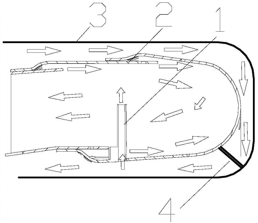
[0020] In order to solve the problems of the prior art, the present invention provides a flame stabilizer for a reflux combustion chamber. The flame stabilizer is installed in the head area of ​​the reflux combustion chamber, such as figure 1 As shown, 12 flame stabilizers 1 are connected to the flame tube 2 at the bottom by welding, the flange 4 is welded to the head wall of the flame tube 2, and the flame tube 2 is bolted to the combustion chamber machine through the other end of the flange 4 The end face of box 3;

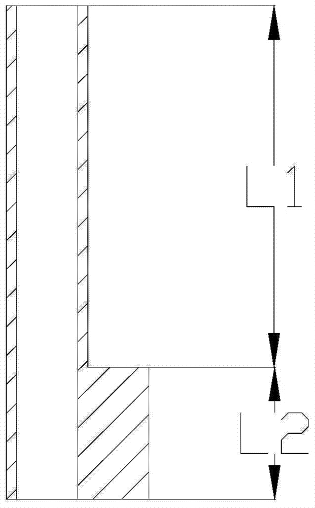
[0021] The flame stabilizer 1 is an integral two-stage body, which is divided into upper and lower sections. The upper section, that is, the L1 section is hollow, and the cross-sectional shape is a semicircular arc ri...


PUM


Abstract

The invention belongs to the technical field of turbine engines, and in particular relates to a flame stabilizer for a recirculation combustion chamber. The cross section of the aerodynamic stabilizing part of the stabilizer is a semicircular arc tube, which has the characteristics of a strong flame stabilizing vortex system and strong flame stabilizing ability; The lower part of the stabilizer adopts an arc-shaped section, which is beneficial to reduce the obstruction of other jet holes and reduce the total pressure loss. The interior of the flame stabilizer is designed as a cavity, which can not only effectively cool the wall of the flame stabilizer, but also supply low-velocity air to a specific area of ​​the combustion chamber to stabilize the flame. The solution of the present invention realizes efficient and stable operation of the combustion chamber through a simple structure, can significantly expand the boundary of fuel-lean flameout, improve combustion efficiency, and reduce production costs at the same time. Tests have proved that jet holes using this cooling method can ensure that the wall life of the jet hole part of the combustion chamber is as long as 300h under the condition that the combustion room rises above 800K and the cooling air is higher than 500K.

Description

Technical field [0001] The invention belongs to the technical field of turbine engines, and particularly relates to a flame stabilizer used for a reflux combustion chamber. Background technique [0002] In the main combustion chamber of the turbine engine, due to the large inlet flow rate and relatively small oil and gas conditions, it is easy to cause the engine to stall due to unstable combustion. In this case, large-scale improvement of the combustion chamber is likely to waste manpower and material resources, and at the same time increase the development cost of the combustion chamber. Summary of the invention [0003] (1) Technical problems to be solved [0004] The technical problem to be solved by the present invention is: how to improve the combustion chamber under small working conditions and high inlet flow rate by locally improving the main combustion zone at the head of the combustion chamber without changing the main structure of the combustion chamber Flame stability...

Claims


Application Information

Patent Timeline
Patent Type & Authority Patents(China)
IPC IPC(8): F23R3/18
Inventor 蔡文哲田颖赵学成翟普
Owner BEIJING POWER MACHINERY INST
Why Eureka
Try Eureka