Wireless energy receiving system

A wireless energy and receiving system technology, applied in electric vehicles, electrical components, transportation and packaging, etc., can solve the problems of diode loss, large loss of four diodes, unfavorable integration and miniaturization of the power supply at the receiving end, and achieve improvement Integration, reduce production costs, improve the effect of conversion efficiency

Active Publication Date: 2016-02-24
深圳市英特源电子有限公司
View PDF4 Cites 5 Cited by
  • Summary
  • Abstract
  • Description
  • Claims
  • Application Information

AI Technical Summary

Problems solved by technology

The former uses four diodes for rectification. Due to the conduction voltage drop of the diodes, when the input current is large, the loss of the four diodes will be large; although the latter replaces the two diodes with two high-voltage power NMOS tubes, it still loses There are two diode losses
At the same time, these diodes and high-voltage power NMOS are discrete devices, which is not conducive to the integration and miniaturization of the power supply part of the receiving end

Method used


Image

  • Wireless energy receiving system
  • Wireless energy receiving system
  • Wireless energy receiving system

Examples


Embodiment Construction

[0025] In order to further illustrate the technical means adopted by the present invention and its effects, the following describes in detail in conjunction with preferred embodiments of the present invention and accompanying drawings.

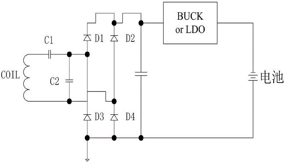
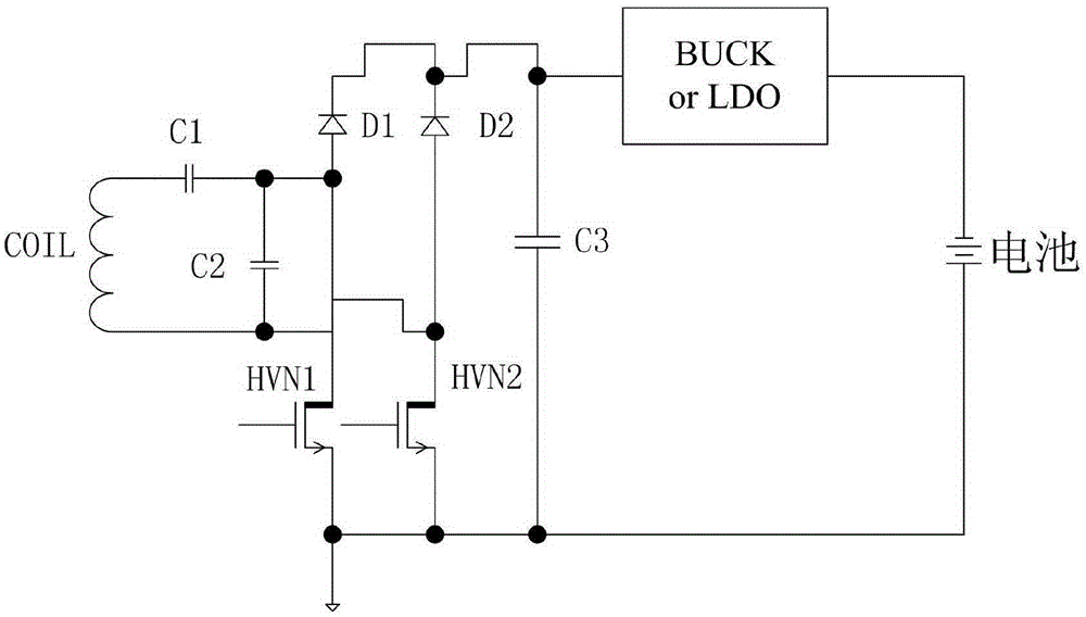
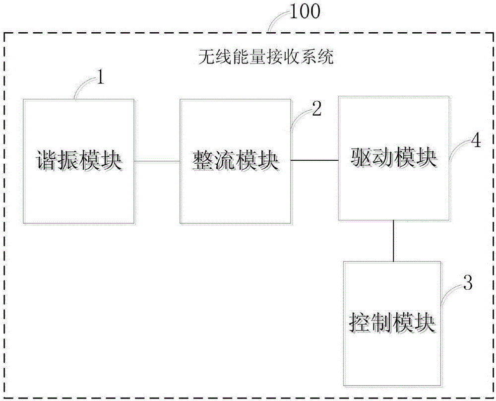
[0026] image 3 It is a block diagram of the wireless energy receiving system 100 in an embodiment of the present invention. In this embodiment, the wireless energy receiving system 100 can be used at a receiving end of wireless charging, such as a handheld terminal supporting wireless charging. The wireless energy receiving system 100 includes a resonance module 1 , a rectification module 2 , a control module 3 and a driving module 4 . The resonant module 1 is used to receive wireless energy sent by the wireless charging transmitter and convert the received wireless energy into an AC voltage signal. The rectification module 2 is electrically connected to the resonance module 1, and the rectification module 2 includes a plurality of field ef...


PUM


Abstract

The invention provides a wireless energy receiving system, which is used for a wireless energy receiving end and includes a resonance module, a rectifier module, a control module and a driving module. The resonance module is used for receiving wireless energy and converting the received wireless energy into alternating voltage signals. The rectifier module is electrically connected to the resonance module, includes a plurality of field effect transistors and is used for performing rectification on the alternating voltage signals. The control module is electrically connected to the rectifier module, and is used for outputting a plurality of sequential control signals to control the plurality of field effect transistors in one-to-one correspondence. The driving module is electrically connected to the rectifier module and the control module, and is used for amplifying the plurality of sequential control signals to control the on-off states of the plurality of field effect transistors. The abovementioned wireless energy receiving system adopts the four high-voltage power field effect transistors to perform full-bridge rectification on the alternating voltage converted from the received wireless energy, thereby effectively improving conversion efficiency of a rectifier bridge.

Description

technical field [0001] The invention relates to a wireless charging system, in particular to a wireless energy receiving system with full-bridge synchronous rectification. Background technique [0002] Due to the advantages of convenience and safety, wireless charging technology is increasingly used by mainstream mobile phone manufacturers. There are currently two mainstream control methods: magnetic induction and magnetic resonance. No matter which control method is used, for the receiving end, it is necessary to convert the AC voltage signal into a DC voltage signal in order to charge the battery of the mobile phone. [0003] However, the existing power supply part of the receiving end generally adopts such as figure 1 The four diodes shown perform full-bridge rectification, plus a step-down conversion chip to charge the mobile phone battery; or use such as figure 2 The two diodes and two high-voltage power NMOS transistors shown are used for full-bridge rectification,...

Claims


Application Information

Patent Timeline
Patent Type & Authority Applications(China)
IPC IPC(8): H02J7/02H02J50/05
CPCH02J7/025
Inventor 田欢裘伟光
Owner 深圳市英特源电子有限公司
Why Eureka
Try Eureka