
Speed reducer provided with air cooling, oil collecting, lubricating and clearance eliminating structure

A reducer and oil collecting technology, which is applied in the direction of gear lubrication/cooling, belt/chain/gear, transmission parts, etc., can solve the problems of poor heat dissipation performance of the reducer, poor gear lubrication effect, and elevated lubricating oil temperature, etc., to achieve Improve lubrication and cooling effects, prolong service life, eliminate the effect of gear fit clearance

Inactive Publication Date: 2016-02-17
QIJIANG BENLI GEAR CO LTD
View PDF5 Cites 2 Cited by
  • Summary
  • Abstract
  • Description
  • Claims
  • Application Information

AI Technical Summary

Problems solved by technology

[0006] In view of this, the purpose of the present invention is to provide a reducer with air cooling, oil-collecting lubrication and anti-backlash structure to solve the problem of poor heat dissipation of the reducer in the prior art, and the temperature of the lubricating oil will rise when the reducer works for a long time. The technical problem of high performance decline; and the technical problem of solving the technical problem that the gear clearance of the reducer gear in the prior art will increase during the long-term use; and the technical problem of solving the poor lubrication effect of the gear in the existing reducer

Method used


Image

  • Speed reducer provided with air cooling, oil collecting, lubricating and clearance eliminating structure
  • Speed reducer provided with air cooling, oil collecting, lubricating and clearance eliminating structure
  • Speed reducer provided with air cooling, oil collecting, lubricating and clearance eliminating structure

Examples


Embodiment Construction

[0019] The present invention will be further described below in conjunction with the accompanying drawings and embodiments.

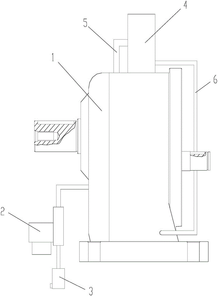
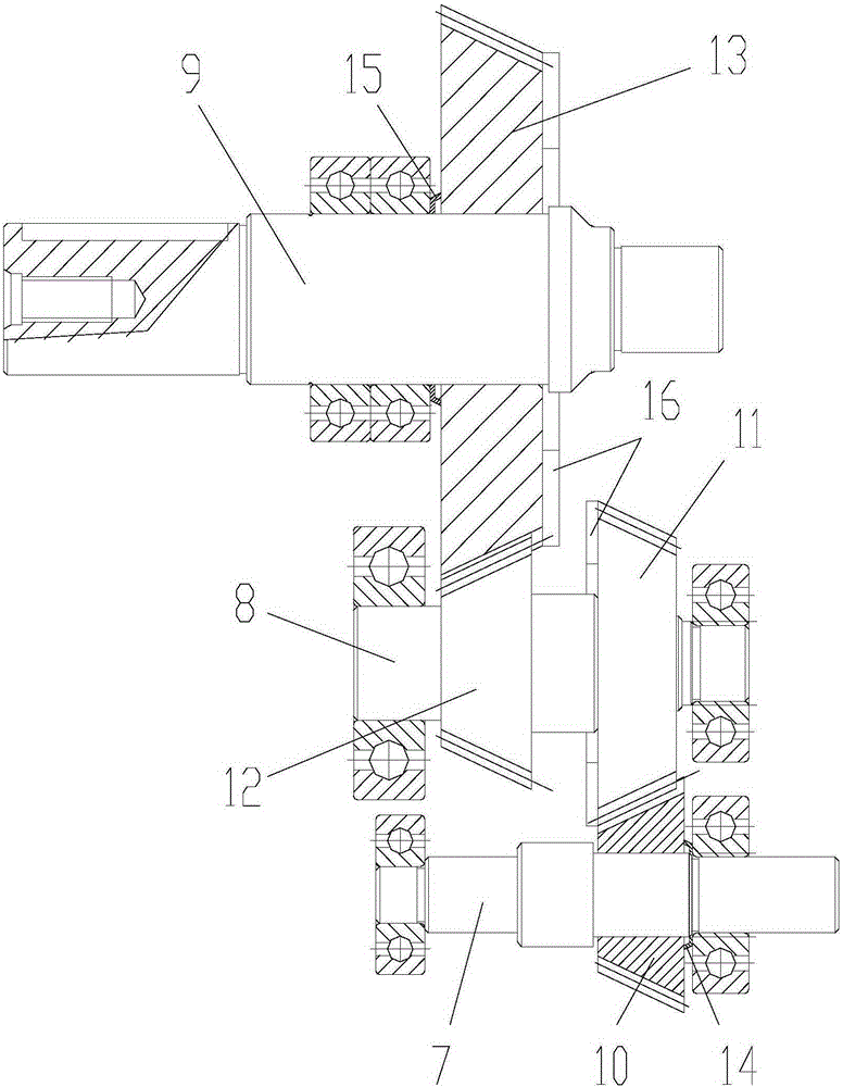
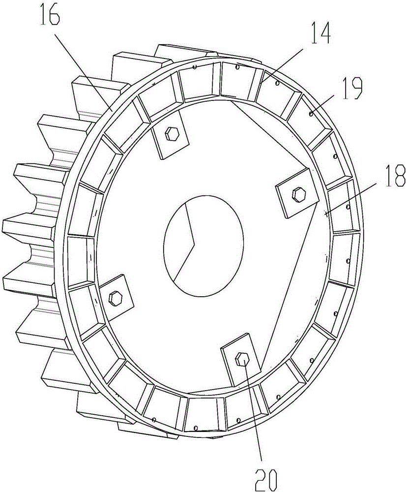
[0020] As shown in the figure, the reducer with air-cooled, oil-collecting lubrication and anti-backlash structure in this embodiment includes a reducer casing 1 and a gear transmission mechanism arranged in the reducer casing, and also includes an air-cooling device, the air-cooled The device includes a fan 2, an air filter 3 and an oil-gas separator 4, the air filter is connected to the air inlet of the fan, the air outlet of the fan is located outside the reducer, and the reducer housing is also provided with a drain Gas pipe 5 and oil return pipe 6, the gas outlet end of the exhaust pipe is connected with the inlet end of the oil-gas separator, the oil outlet end of the oil-gas separator is connected with the oil inlet end of the oil return pipe, and the oil outlet of the oil return pipe The end is located in the lubricating oil in the reducer housi...


PUM


Abstract

The invention discloses a speed reducer provided with an air cooling, oil collecting, lubricating and clearance eliminating structure. The speed reducer comprises a speed reducer shell, a gear transmission mechanism, an air cooling device and an oil collecting device. The air cooling device comprises a draught fan, an air filter and an oil-gas separator. The speed reducer further comprises a first belleville spring used for applying axial thrust to a first bevel gear and a second belleville spring used for applying axial thrust to a fourth bevel gear. The oil collecting device comprises a circular pipe body, a partition board, an oil storage cavity, an oil inlet and an oil outlet. According to the speed reducer, the gears and lubricating oil in the speed reducer shell are cooled through the air cooling device, and thus the problems that due to long-term working of the speed reducer, the temperature of the lubricating oil is increased, and the performance is reduced can be solved; in addition, when the gears are abraded, the belleville springs can automatically push the first bevel gear and the fourth bevel gear to move in the axial direction, and thus a gear fit clearance caused by frictional abrasion is eliminated; furthermore, the lubricating oil is carried into a gear engagement area through the oil collecting device to lubricate the gears, and thus the lubricating and cooling effects on the gears can be improved.

Description

technical field [0001] The invention relates to a speed reduction device, in particular to a speed reducer. Background technique [0002] The reducer is a transmission device used to convert the high-speed low-torque power output by the electric motor or internal combustion engine into low-speed high-torque output. [0003] The reducer is generally composed of the reducer casing and the gear transmission mechanism arranged in the reducer casing. When the reducer is working, the friction between the meshing gears will generate a lot of heat. In the prior art, the reducer generally passes through the reducer casing. Set lubricating oil to lubricate and cool the meshing gears, but the heat dissipation performance of the existing reducer is poor. The reduction will accelerate the wear of the gears, which in turn will shorten the life of the reducer. [0004] During the transmission process of the reducer, its tooth surface is prone to friction and wear. Friction and wear will ...

Claims


Application Information

Patent Timeline
Patent Type & Authority Applications(China)
IPC IPC(8): F16H57/04F16H1/22F16H57/12
CPCF16H57/0413F16H1/22F16H57/0416F16H57/0473F16H57/0495F16H57/12F16H2057/127
Inventor 吴思伟刘永平贺良中官志远
Owner QIJIANG BENLI GEAR CO LTD
Learn More