Herringbone tooth surface gear transmission mechanism and tooth milling method for herringbone tooth surface gear of herringbone tooth surface gear transmission mechanism

A transmission mechanism, herringbone tooth technology, applied in the direction of gear transmission, transmission, components with teeth, etc., can solve the problems such as the inability to effectively utilize the tooth width to carry, the carrying capacity is not high, the degree of coincidence is small, etc. The effect of popularization, large carrying capacity and increased carrying capacity

Active Publication Date: 2016-02-17
宁波市吉尔传动部件有限公司
View PDF15 Cites 6 Cited by
  • Summary
  • Abstract
  • Description
  • Claims
  • Application Information

AI Technical Summary

Problems solved by technology

[0010] However, the above-mentioned types of face gears have the following problems: For traditional straight teeth and Coniface face gears, there are characteristics of small coincidence, low load capacity, and accompanying vibration and noise; for helical teeth and Conical face gears, due to the introduction of the helix angle , which will weaken the advantage of the small wheel without axial force in the face gear transmission; the above-mentioned types of face gear transmissions need to be designed as a point-contact meshing form (to avoid edge contact caused by installation errors, support deformation, or gear teeth cannot Contact and other adverse effects), can not effectively use its tooth width load

Method used


Image

  • Herringbone tooth surface gear transmission mechanism and tooth milling method for herringbone tooth surface gear of herringbone tooth surface gear transmission mechanism
  • Herringbone tooth surface gear transmission mechanism and tooth milling method for herringbone tooth surface gear of herringbone tooth surface gear transmission mechanism
  • Herringbone tooth surface gear transmission mechanism and tooth milling method for herringbone tooth surface gear of herringbone tooth surface gear transmission mechanism

Examples


Embodiment Construction

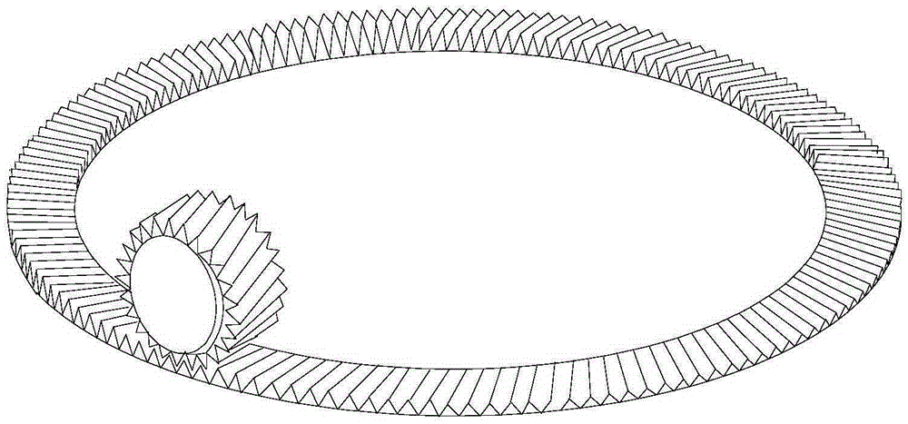
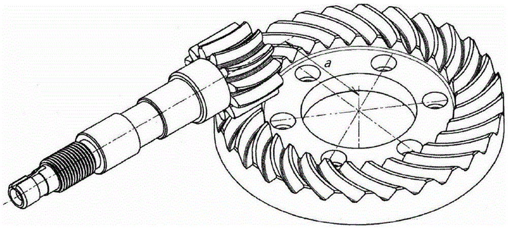
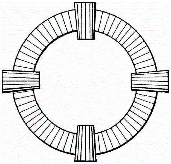
[0044] Such as Figure 4 , Figure 5 and Figure 6 As shown, the herringbone gear transmission mechanism of the present invention includes a herringbone gear 1 and a herringbone cylindrical gear 2 whose axes are perpendicular to each other and meshed with each other. The said herringbone gear 1 includes a disc-shaped wheel Body 9 and the gear shaft 10 located in the middle of the disc-shaped wheel body 9, one side surface of the disc-shaped wheel body 9 is provided with the first herringbone teeth in the ring with the center of the gear shaft 10 as the center of the circle 3. The second herringbone tooth 4 is arranged on the outer circumference of the wheel of the herringbone cylindrical gear 2, and the first herringbone tooth 3 is composed of the first right-handed gear tooth 7 and the first left-handed gear tooth in a herringbone shape. The second herringbone tooth 4 is composed of the second left-handed gear tooth 5 and the second right-handed gear tooth 6 that are docked...


PUM


Abstract

The invention discloses a herringbone tooth surface gear transmission mechanism. The herringbone tooth surface gear transmission mechanism comprises a herringbone tooth surface gear and a herringbone tooth cylindrical gear. The herringbone tooth surface gear comprises a disc gear body and a gear shaft. First herringbone teeth annually distributed are arranged on the surface of one side of the disc gear body. Second herringbone teeth are arranged on the periphery of a gear body of the herringbone tooth cylindrical gear. Each first herringbone tooth is composed of a first right-handed gear tooth and a first left-handed gear tooth which are connected to be herringbone in a butt joint manner. Each second herringbone tooth is composed of a second left-handed gear tooth and a second right-handed gear tooth which are connected to be herringbone in a butt joint manner. The second left-handed gear teeth are meshed with the first right-handed gear teeth. The second right-handed gear teeth are meshed with the first left-handed gear teeth. The invention further discloses a tooth milling method for the herringbone tooth surface gear in the herringbone tooth surface gear transmission mechanism. The herringbone tooth surface gear transmission mechanism is high in bearing capacity, good in meshing performance, stable in transmission, low in noise and high in practicability. By means of the tooth milling method for the herringbone tooth surface gear, the tooth width of the herringbone tooth surface gear can be utilized to the maximum extent.

Description

technical field [0001] The invention belongs to the technical field of gear transmission, and in particular relates to a herringbone tooth surface gear transmission mechanism and a tooth milling method of the herringbone tooth surface gear. Background technique [0002] As a new type of transmission, face gear has many advantages, such as high coincidence degree, high load capacity, used in power branch transmission, and high shunt precision. In view of its transmission advantages, it was first used in the main transmission system of helicopters. With the progress of manufacturing technology, face gear transmission has also been applied in transmission fields such as vehicles and wind power. [0003] Face gear transmission is a transmission method in which cylindrical gears and bevel gears are meshed. The first to enter the practical application stage is spur gear transmission, that is, the meshing transmission mechanism composed of spur gears and face gears. In order to fu...

Claims


Application Information

Patent Timeline
Patent Type & Authority Applications(China)
IPC IPC(8): F16H1/18F16H55/17B23F7/00
CPCB23F7/00F16H1/18F16H55/17
Inventor 彭先龙
Owner 宁波市吉尔传动部件有限公司
Why Eureka
Try Eureka