
Vehicle alarm device

A technology of alarms and relays, which is applied in the field of vehicle alarms and can solve problems such as car serial collisions

Inactive Publication Date: 2016-02-17
SHAANXI EYINHE ELECTRONICS
View PDF0 Cites 0 Cited by
  • Summary
  • Abstract
  • Description
  • Claims
  • Application Information

AI Technical Summary

Problems solved by technology

[0002] On the expressway, in an emergency situation, the driver of the car following the emergency brake will cause the driver of the car behind to react too late, often causing serious accidents of multiple cars colliding in series. Therefore, it is necessary to design An emergency brake alarm that gives a brake alarm in time to avoid the expansion of the situation to the greatest extent

Method used


Image

  • Vehicle alarm device
  • Vehicle alarm device

Examples


Embodiment 1

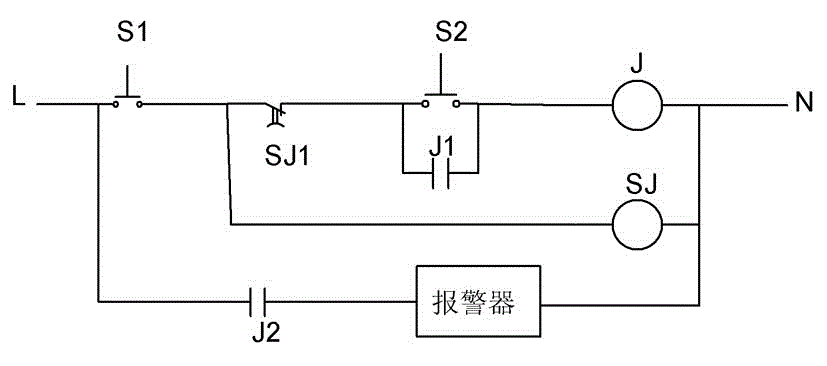
[0014] Such as figure 1 As shown, an emergency brake alarm includes a first switch S1 for detecting the front action of the brake, a second switch S2 for detecting the back action of the brake, a relay, a delay relay and a wireless alarm signal. Alarm; the positive pole L of the DC power supply is connected to the negative pole N of the DC power supply through the first switch S1, the normally closed contact SJ1 of the delay relay, the second switch S2 and the coil J of the relay, and the first normally open contact of the relay J1 is connected in parallel with the second switch S2; one end of the coil SJ of the delay relay is connected to the negative pole N of the DC power supply, and the other end is connected to the connection point between the first switch S1 and the normally closed contact SJ1 of the delay relay, and the positive pole L of the DC power supply is sequentially passed through The second normally open contact J2 of the relay and the alarm are connected with ...

Embodiment 2

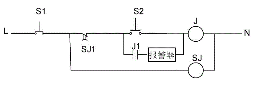
[0017] Such as figure 2 As shown, the difference between the circuit of embodiment 2 and embodiment 1 is that the connection method of the alarm is different. In embodiment 2, the alarm is connected in series with the first normally open contact J1 of the relay, which can also realize the timely sending of alarm signals. Features. In fact, the same effect can be achieved if the alarm is connected in series with the relay coil J or the normally closed contact SJ1 of the delay relay.

[0018] In addition, for a car with an anti-lock braking system (ABS), the signal output by the anti-lock braking system can also be used to control the alarm.

[0019] The alarm device sends out a wireless alarm signal. According to the wireless receiving device on other cars, the alarm signal sent by the alarm device is received through the antenna. After the adjacent car receives the alarm signal, it will give sound and light instructions on the car to remind the driver. There are emergency b...


PUM


Abstract

The invention discloses a vehicle alarm device, characterized by comprising a first switch, a second switch, a relay, a time-delay relay, and an alarm apparatus. The first switch is used to detect brake early-course operation, and the second switch is used to detect brake late-course operation. The alarm apparatus is used to give out wireless alerting signals. The anode of a DC power supply is connected with the cathode of the DC power supply through the first switch, the normally-closed contact of the time-delay relay, the second switch, and the coil of the relay in sequence. The normally open contact of the relay is connected with the second switch in parallel. One end of the coil of the time-delay relay is connected with the cathode of the DC power supply, and the other end is connected with the junction of the first switch and the normally-closed contact of the time-delay relay. The relay is connected in series with the alarm apparatus through the normally open contact of the relay, so as to control operation of the alarm apparatus. The vehicle alarm device can detect whether a brake is pressed through two switches when a vehicle brakes in emergency, so as to start the alarm apparatus to give out a braking signal to vehicles nearby, and prevent accidents of multi-vehicle chain-reaction collision.

Description

technical field [0001] The invention relates to a vehicle alarm. Background technique [0002] On the expressway, in an emergency situation, the driver of the car following the emergency brake will cause the driver of the car behind to react too late, often causing serious accidents of multiple cars colliding in series. Therefore, it is necessary to design The utility model relates to an emergency brake alarm, which can give a brake alarm in time and avoid the expansion of the situation to the greatest extent. Contents of the invention [0003] In order to solve the above-mentioned existing shortcomings, the main purpose of the present invention is to provide a practical vehicle alarm, which can send a braking signal to notify nearby vehicles in time when the vehicle is in emergency braking, so as to avoid multiple vehicles in a chain. crash accident. [0004] In order to achieve the above-mentioned purpose, a vehicle alarm of the present invention adopts the following t...

Claims


Application Information

Patent Timeline
Patent Type & Authority Applications(China)
IPC IPC(8): B60Q9/00B60T17/22
Inventor 李洋陈刚杨树峰李涛肖剑林李华清
Owner SHAANXI EYINHE ELECTRONICS
Learn More