
an electric hammer

An electric hammer and collet technology, applied in the direction of striking tools, light impact tools, manufacturing tools, etc., can solve the problems of long replacement time, increased disassembly and assembly force, and insufficient hammering force, and achieve disassembly and maintenance. The wearing parts are convenient, improve the hammering force, and prolong the service life.

Active Publication Date: 2018-08-24
JIANGSU HENGFENG ELECTRIC TOOLS
View PDF7 Cites 2 Cited by
  • Summary
  • Abstract
  • Description
  • Claims
  • Application Information

AI Technical Summary

Problems solved by technology

[0002] At present, the electric hammers on the market have the following disadvantages: 1) There is a gap between the drill bit and the impactor, and it is necessary to force forward when punching the drill; 2) The chuck part adopts operations such as pressing, lifting, and pulling to position, and the replacement time is long. It is also relatively cumbersome; 3) The wearing parts such as the drill bushing assembly need to be replaced in a special repair shop, and all the auxiliary parts such as the circlips and bearings connected to it need to be removed during the replacement, which is not convenient for daily maintenance; 4) Chuck The connection structure with the cylinder body is complex, and the disassembly and assembly efforts are increased; 5) When in use, the hammer's hammering force is not strong enough, and the working efficiency cannot achieve the expected strength effect

Method used


Image

  • an electric hammer
  • an electric hammer
  • an electric hammer

Examples


Embodiment Construction

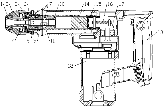
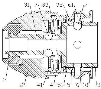
[0019] Such as Figure 1 to Figure 4 As shown, an electric hammer includes a chuck, a housing 12, a cylinder assembly and a transmission assembly arranged in the housing 12, a handle 13 is provided on the side of the housing 12, and the chuck includes a chuck body 2, a square The sleeve 3 and the jacket 6, the square sleeve 3 has a convex structure composed of a small diameter part 31 and a large diameter part 32, the side of the large diameter part 32 is clamped with the boss 61 inside the jacket 6 through the steel ball 7, the jacket 6 is located A lower spring 5 is sleeved between the part above the boss 61 and the large diameter portion 32, the top of the lower spring 5 is provided with a fixed pad 51, and the side of the small diameter portion 31 is provided with a limiting hole 33, and the length of the limiting hole 33 is longer than that of the steel plate. The diameter of the ball 7, the upper spring 4 is set between the small diameter part 31 and the jacket 6, the bo...


PUM


Abstract

The invention discloses an electric hammer which comprises a chuck, a shell, an air cylinder assembly and a transmission assembly, wherein the air cylinder assembly and the transmission assembly are arranged in the shell. The side face of the shell is provided with a handle. The chuck comprises a chuck body, a tetragonal sleeve and a clamp cover. The air cylinder assembly comprises a cylinder body. A drill brush hole and a piston hole are formed in the front part and the rear part of the cylinder body respectively. A first step at the front portion of the cylinder body extends into the tetragonal sleeve. According to the electric hammer, a drill bit is inserted and then directly collides with an impact oscillator, and impact drilling is easier; the chuck is convenient to assemble, the drill bit is inserted into and pulled out directly and quickly through cooperation of steel balls and springs; by adjusting a connection structure between the cylinder body and an impact sleeve and a connection structure between the cylinder body and the chuck, the length of the air cylinder assembly is shorter compared with a traditional air cylinder assembly; through clamping of the steel balls, quick-wear parts are more convenient to disassemble, assemble and maintain, and the service life of the electric hammer is prolonged greatly; and furthermore, the hammering strength on a drill bush assembly of a punch hammer is improved by enlarging the hole diameter of the large piston hole, and the working efficiency of the electric hammer is improved greatly.

Description

technical field [0001] The invention relates to an electric hammer. Background technique [0002] At present, the electric hammers on the market have the following disadvantages: 1) There is a gap between the drill bit and the impactor, and it is necessary to force forward when punching the drill; 2) The chuck part adopts operations such as pressing, lifting, and pulling to position, and the replacement time is long. It is also relatively cumbersome; 3) The wearing parts such as the drill sleeve assembly need to be replaced in a special repair shop, and all the auxiliary parts such as the circlips and bearings connected to it need to be removed during the replacement, which is not convenient for daily maintenance; 4) The chuck The connection structure with the cylinder body is complicated, and the disassembly and assembly efforts are increased; 5) When in use, the impact force of the impact hammer is not strong enough, and the working efficiency cannot achieve the expected s...

Claims


Application Information

Patent Timeline
Patent Type & Authority Patents(China)
IPC IPC(8): B25D11/04B25D17/08B25D17/00
Inventor 李强成英李慧萍
Owner JIANGSU HENGFENG ELECTRIC TOOLS
Learn More