
Manufacturing process method of aluminum alloy chassis end of standard EMU

A technology for EMUs and aluminum alloys, applied in manufacturing tools, vehicle parts, metal processing, etc., can solve the problem that the flatness and size of the front plate at the end of the chassis are difficult to control, affect the overall size and welding of the chassis, and cannot guarantee the overall size Requirements and other issues to achieve the effect of improving the overall welding quality and production efficiency, improving the overall welding quality, and improving welding accessibility

Active Publication Date: 2017-11-10
CRRC CHANGCHUN RAILWAY VEHICLES CO LTD
View PDF6 Cites 0 Cited by
  • Summary
  • Abstract
  • Description
  • Claims
  • Application Information

AI Technical Summary

Problems solved by technology

[0003] 1. The coupler seat of the stressed structure is 80MM thick aluminum profile, which is 2.28 times the thickness of the traditional coupler seat. The welding deformation after welding is relatively large, and the external dimension requirements cannot be guaranteed;
[0004] 2. It is difficult to control the flatness and size of the front plate at the end of the chassis;
[0005] 3. The connecting plate of the new structure is a plate structure of 3240*1240*20. After welding, the flatness is required to be 3mm, which cannot be achieved by traditional technology
[0006] 4. It is difficult to control the flatness with the bottom frame, which affects the overall size and welding of the bottom frame

Method used


Image

  • Manufacturing process method of aluminum alloy chassis end of standard EMU
  • Manufacturing process method of aluminum alloy chassis end of standard EMU
  • Manufacturing process method of aluminum alloy chassis end of standard EMU

Examples


Embodiment Construction

[0032] Material inspection: check the surface quality of the material, oil stains, burrs are not allowed, bumps and scratches are not allowed to exceed 0.1 times the thickness of the plate, and the maximum does not exceed 0.5mm; according to the production order, compare the length and width dimensions of the material with reference to the drawings , Socket form, thickness dimension, flatness, etc. shall be inspected.

[0033] Grinding and cleaning: Lift the parts to the grinding stand or platform, and use dry cotton cloth to remove the dust on the surface of the profile and parts. Use a straight handle grinder to grind the weld area, the grinding area is 15-25mm, and the grinding is required until the metallic luster is exposed.

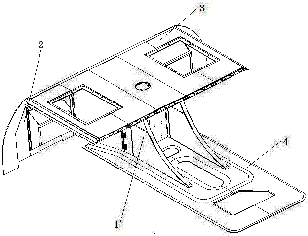
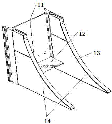
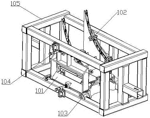
[0034] refer to figure 1 , optimize the aluminum structure at the end of the underframe, and divide the overall structure of the end of the underframe into end beam traction beam synthesis 1, end beam front plate 2, end beam bottom plate 3, and und...


PUM


Abstract

The invention relates to a manufacturing process of the ends of an aluminum alloy underframe of a standard motor train unit. The whole structure of each end of the underframe is divided into four parts including the synthesis of an end beam traction beam, an end beam front end plate, an end beam bottom plate and an underframe connecting plate; the synthetic process of an underframe end beam comprises five steps of synthesizing, assembling and welding the end beam traction beam, synthesizing, assembling and welding the end beam front end plate, assembling and welding the end beam traction beam, the end beam bottom plate and the end beam front end plate, assembling and welding the underframe connecting plate and processing the end beam synthesized underframe connecting plate; both the end beam bottom plate and the underframe connecting plate are welded by adopting friction stir welding, so that the whole size and the flatness requirement are guaranteed. According to the manufacturing process, blocking welding and blocking assembly are adopted, so that the whole structure is simplified, the tooling design is reasonable, the welding reachability is increased by using a positioner, the welding difficulty is reduced, and the product welding quality is increased. The size does not need to be adjusted after welding, so that the labor intensity is reduced, and the whole welding quality of the position and the production efficiency are increased. The flatness design requirement of the front end plate is satisfied after the ends of the underframe is synthesized, assembled and welded.

Description

technical field [0001] The invention relates to a new synthesis welding process technology for the end part of the aluminum alloy car body underframe of a high-speed car. Background technique [0002] The end of the underframe of the aluminum alloy car body of the Chinese standard 350km / h EMU is different from the end of the underframe of the existing CRH380 series EMU and CRH250 series EMU. It is a new structure independently designed and developed by the company. The end of the underframe is an important structure of the aluminum alloy car body. The overall design structure is complex, the welding deformation is difficult to control, and the manufacturing cycle is long. The main process difficulties of adopting traditional process methods: [0003] 1. The coupler seat of the stressed structure is 80MM thick aluminum profile, which is 2.28 times the thickness of the traditional coupler seat. The welding deformation after welding is relatively large, and the external dimens...

Claims


Application Information

Patent Timeline
Patent Type & Authority Patents(China)
IPC IPC(8): B23K20/12B23K20/24B23K20/26B23K37/04
CPCB23K20/12B23K20/24B23K20/26B23K37/0443B23K2101/006B23K2103/10
Inventor 王永亮王世君黄林
Owner CRRC CHANGCHUN RAILWAY VEHICLES CO LTD
Learn More