Longitrorse complex excitation ultrasonic motor, driving platform and driving method thereof
A technology of composite excitation and ultrasonic motor, which is applied in the direction of generator/motor, piezoelectric effect/electrostrictive or magnetostrictive motor, electrical components, etc., can solve the problem of small vibration amplitude and poor output performance of ultrasonic motor Ideal, small effective contact area and other issues, to achieve the effect of large vibration amplitude, improved output performance of the whole machine, large application and development prospects
- Summary
- Abstract
- Description
- Claims
- Application Information
AI Technical Summary
Problems solved by technology
Method used
Image
Examples
specific Embodiment approach 1
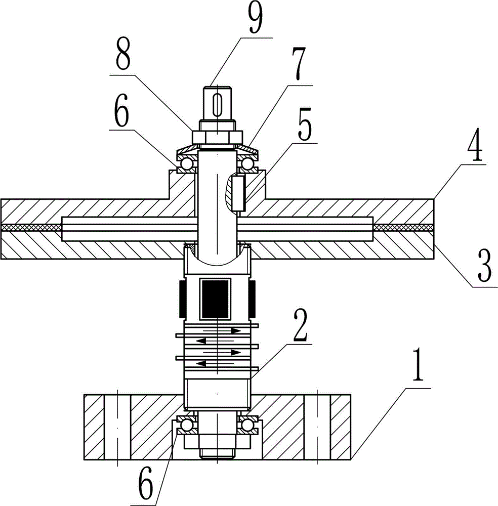
[0037] Specific implementation mode one: combine Figure 1~Figure 11 , Figure 14~Figure 16 This embodiment will be described. This implementation mode provides a specific implementation scheme of a vertical-torsion composite excitation ultrasonic motor. The longitudinal-torsion composite excitation ultrasonic motor is mainly composed of a fixed base 1, a first elastic body 2, a second elastic body 3, a rotating body 4, a key 5, a thrust ball bearing 6, a butterfly spring 7, a nut 8 and an output shaft 9 composition.
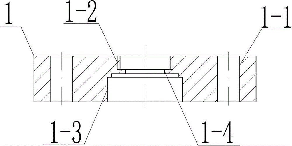
[0038] The fixed base 1 is a plate structure, and the end surface of one side of the fixed base 1 is evenly provided with n through holes 1-1 structures along the circumferential direction, which are used to realize the fixed installation of the present invention, wherein n is greater than or equal to 1 Integer; the central position of the end surface on one side of the fixed base 1 is provided with a threaded hole 1-2 structure, which is used for the externa...
specific Embodiment approach 2
[0044] Specific implementation mode two: combination Figure 13~Figure 19 This embodiment will be described. This implementation mode provides a specific implementation scheme of a driving platform using a longitudinal-torsion compound vibration excitation ultrasonic motor. The drive platform using the longitudinal-torsion composite excitation ultrasonic motor is mainly composed of a fixed outer frame 1, a first elastic body 2, a second elastic body 3, a rotating platform 4, a rolling body 5, a thrust ball bearing 6, and a disc spring 7. The fastening connector 8 and the inner hexagonal bolt 9 are composed of the second elastic body 3 in the driving platform using the longitudinal-torsion composite excitation ultrasonic motor and the structural composition of the second elastic body 3 in the first specific embodiment. The connection is the same.
[0045] The fixed outer frame 1 is a thin-walled ring structure with a flange at one end, and q through holes 1-1 structures are e...
specific Embodiment approach 3
[0050] Embodiment 3: This embodiment provides a specific embodiment of a vertical-torsion compound vibration excitation ultrasonic motor and a driving method of a driving platform using the motor.
[0051] The specific implementation of the longitudinal-twisting compound vibration excitation ultrasonic motor and the driving method of the driving platform using the motor is as follows: the excitation group A passes an AC excitation electrical signal of a certain ultrasonic frequency (generally greater than 16kHz), Excite the first elastic body 2 where it is located to generate a torsional vibration mode; the excitation group B passes an AC excitation electrical signal of the same ultrasonic frequency (generally greater than 16kHz), and the excited longitudinal vibration excites the second elastic body 3 to generate bending vibration mode; the excitation group A and the excitation group B pass the same amplitude of the AC excitation electric signal, and the driving phase differen...
PUM
 Abstract
Description
Claims
Application Information
 - R&D
- Intellectual Property
- Life Sciences
- Materials
- Tech Scout
- Unparalleled Data Quality
- Higher Quality Content
- 60% Fewer Hallucinations
Browse by: Latest US Patents, China's latest patents, Technical Efficacy Thesaurus, Application Domain, Technology Topic, Popular Technical Reports.
© 2025 PatSnap. All rights reserved.Legal|Privacy policy|Modern Slavery Act Transparency Statement|Sitemap|About US| Contact US: help@patsnap.com


