
Hybrid braking excitation structure for maglev train

A magnetic levitation train, hybrid technology, applied in the direction of permanent magnet clutch/brake, asynchronous inductive clutch/brake, electric braking system, etc., can solve the problems of lack of fail-safe guidance, affecting braking effect, heating of excitation coil, etc. , to achieve the effect of energy saving and thermal management, improve reliability and safety, and reduce power loss

Inactive Publication Date: 2016-02-03
ZHEJIANG UNIV
View PDF5 Cites 18 Cited by
  • Summary
  • Abstract
  • Description
  • Claims
  • Application Information

AI Technical Summary

Problems solved by technology

This kind of excitation structure uses the excitation current to perform braking control during the entire braking process, so the energy loss will be too high due to excessive excitation power, and the resulting heating of the excitation coil will affect the braking effect.
Secondly, when the power supply is cut off when the train is parked, the natural eddy current braking system cannot work
In addition, when the magnetic levitation train has some bad working conditions and the excitation circuit system loses power, the ordinary eddy current braking system will completely fail due to the lack of excitation current, lacking fail-safe guidance
To this end, ICE3 installed a large-capacity nickel-cadmium battery as a backup power supply, and additionally installed an additional friction braking system as a cold backup redundancy, but the weakness of the ordinary eddy current track braking system itself still exists, and it affects the magnetic levitation train. Lightweight
[0004] In view of the above problems, there is a lack of new brake systems for maglev trains in the prior art, and effective braking of maglev trains can be achieved through rational design of key components and structures in the brake system

Method used


Image

  • Hybrid braking excitation structure for maglev train
  • Hybrid braking excitation structure for maglev train
  • Hybrid braking excitation structure for maglev train

Examples


Embodiment Construction

[0030] The present invention will be further described below in conjunction with accompanying drawing.

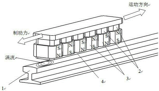
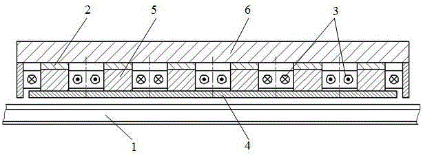
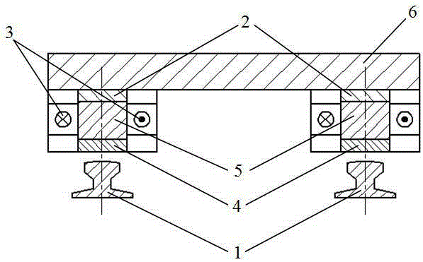
[0031] Such as figure 1 As shown, the present invention mainly arranges a plurality of magnetic poles composed of electromagnets and permanent magnets in the direction of the rails, and is installed at the bottom of the train directly above the rails: the magnetic poles include iron core 5, armature coil 3 and permanent magnets 2. The magnetic field direction of the permanent magnet 2 is perpendicular to the horizontal plane, and the iron cores 5 are arranged at intervals in the direction of the rail. The armature coil 3 with the excitation current is wound around each iron core 5 horizontally, and the permanent magnet 2 is installed on the top of the iron core 5. Thereby forming magnetic poles; the upper end of each permanent magnet 2 is equipped with a yoke 6 in the direction of the rail, and the lower end of each iron core 5 is equipped with a wear plate 4 .

[0032] Su...


PUM


Abstract

The invention discloses a hybrid braking excitation structure for a maglev train. Magnetic poles formed by electromagnets and permanent magnets are arranged along the rail direction and are installed on the bottom of the maglev train right over rails. Each magnetic pole comprises a core, an armature coil, and a permanent magnet. The cores are arranged at intervals along the rail direction. The horizontal periphery of each core is wrapped in the armature coil provided with exciting current. The top of each core is equipped with the corresponding permanent magnet such that the magnetic poles are formed. The top of the permanent magnets are equipped with a magnet yoke along the rail direction. The bottoms of the cores are equipped with a wearing plate. By means of the adjustment of exciting current in an exciting coil, a dynamic maglev train braking process is achieved. By means of reverse excitation, a braking system is simply repositioned. The magnetic force of the permanent magnets enhances eddy current braking control and friction braking effects. The hybrid braking excitation structure reduces the heating of the system, achieves an energy-saving effect and heat management of the system, and is provided with a braking operation mode with safe fault guidance.

Description

technical field [0001] The invention relates to a train braking structure, in particular to a hybrid braking excitation structure for a magnetic levitation train. Background technique [0002] As a new type of ground transportation, the maglev train has the advantages of fast speed, stable operation, low noise, and small environmental impact. Because of its high speed, the braking system of maglev trains is more complicated and important than that of ordinary trains. At present, maglev trains generally adopt a combination of dynamic braking, mechanical friction braking and eddy current braking. The dynamic braking method, that is, electric braking, changes the current phase sequence of the motor, so that the original motor output force is reversed into a braking force. It has the advantages of energy saving, environmental protection, and good control performance. However, due to capacity limitations, Safety considerations and requirements for trailer braking, emergency bra...

Claims


Application Information

Patent Timeline
IPC IPC(8): H02K49/04H02K49/10B60L7/26
CPCY02T10/64
Inventor 马吉恩钟云龙方攸同黄晓艳卢琴芬张健周晶
Owner ZHEJIANG UNIV
Learn More