
Acting cylinder and booster cylinder separated engine

A technology for working cylinders and engines, which is applied in the direction of engine components, combustion engines, machines/engines, etc. It can solve the problems of poor lubrication, mutual interference, mutual stirring, and long-lasting use of crankcase operating parts, and achieves a simple structure , complete combustion and low cost

Pending Publication Date: 2016-02-03
龚福清 +1
View PDF0 Cites 2 Cited by
  • Summary
  • Abstract
  • Description
  • Claims
  • Application Information

AI Technical Summary

Problems solved by technology

[0002] Existing engines include two-stroke engines and four-stroke engines. Two-stroke engines are simple in structure, light in weight, and only need to rotate once to complete a work. Part of the unburned fresh combustible gas is discharged together with the exhaust gas after combustion, causing waste; the gas for combustion is a mixture of engine oil and gasoline, the combustion is not complete, and the exhaust gas pollution is serious
The lubricating system of the four-stroke engine is relatively good, the sustainable use time is longer, and the running resistance is small, but the crankshaft needs to rotate for two weeks to complete one power cycle
During operation, the upper working cylinder burns and works, and the lower pressurized cylinder pressurizes and supplies air. When the diameters of the upper working cylinder and the lower pressurized cylinder need to be consistent, if they are not consistent, the manufacturing process is more complicated and the manufacturing cost is higher.

Method used


Image

  • Acting cylinder and booster cylinder separated engine
  • Acting cylinder and booster cylinder separated engine
  • Acting cylinder and booster cylinder separated engine

Examples


Embodiment Construction

[0012] The present invention will be described in detail below with reference to the accompanying drawings.

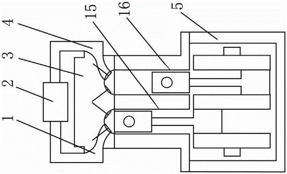
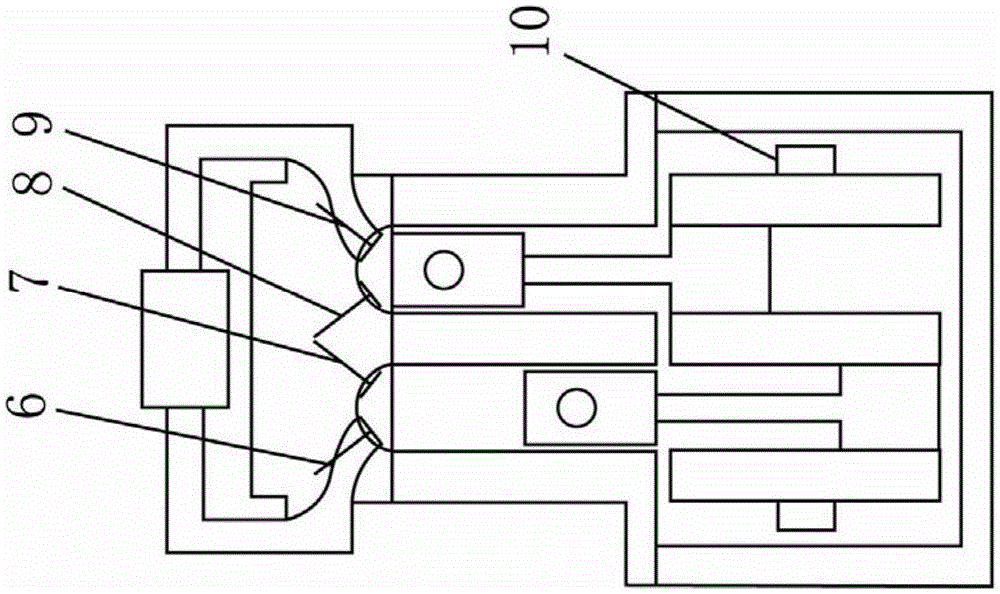
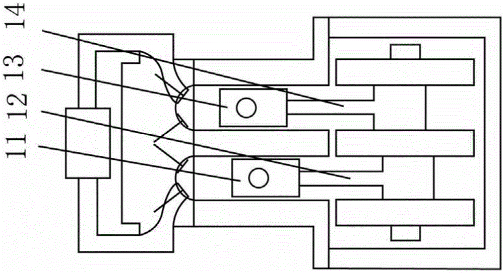
[0013] Work cylinder 16 and booster cylinder 15 are installed on crankcase 5 of the present invention. There is a cylinder head 3 on the power cylinder, a combustion chamber, a power intake valve 9, and a power exhaust valve 8 on the cylinder head. The power intake valve is connected to the intercooler 2 through the exhaust passage 4, and the power exhaust valve is connected to the exhaust pipe. . There is a cylinder head on the supercharged cylinder 15, and a supercharged intake valve 7 and a supercharged exhaust valve 6 are arranged on the cylinder cover. cylinder. The supercharging piston 11 of the supercharging cylinder is connected with the crank throw 10 through the supercharging connecting rod 12; the working piston 13 of the working cylinder is connected with the crank throw 10 through the working connecting rod 14.

[0014] In the present invention, a boost...


PUM


Abstract

The invention relates to an acting cylinder and booster cylinder separated engine. An acting cylinder and a booster cylinder are mounted on a crankshaft box; a cylinder cover is arranged on the acting cylinder; a combustion chamber, an acting intake valve and an exhaust valve are arranged on the cylinder cover; the acting intake valve is connected with an intercooler; and the exhaust valve is connected with an exhaust pipe. A cylinder cover is arranged on the booster cylinder; a booster intake valve and an exhaust valve are arranged on the cylinder cover; the booster exhaust valve is connected with an intercooler; the booster intake valve is connected with the booster cylinder; a booster piston of the booster cylinder is connected with a crankshaft fixture through a booster connecting rod; and an acting piston of the acting cylinder is connected with the crankshaft fixture through an acting connecting rod. The acting cylinder combusts for acting; the booster cylinder boosts for gas supply; the booster gas supply effect can reach an ideal value; and the booster cylinder and the booster piston thereof can change the diameters to supply corresponding intake quantity according to the ideal pressure value requirement of the acting cylinder. The engine is continuous and stable in boosting, is thorough in combustion, saves fuels, is high in power, reduces the pollution, and is simple in structure, low in cost and long in service life.

Description

technical field [0001] The invention relates to an engine with a working cylinder and a supercharging cylinder separated. Background technique [0002] Existing engines include two-stroke engines and four-stroke engines. Two-stroke engines are simple in structure, light in weight, and only need to rotate once to complete a work. Part of the unburned fresh combustible gas is discharged together with the exhaust gas after combustion, causing waste; the gas for combustion is a mixture of engine oil and gasoline, and the combustion is not complete, and the exhaust gas pollution is serious. The lubricating system of the four-stroke engine is relatively good, the sustainable use time is longer, and the running resistance is small, but the crankshaft needs to rotate two weeks to complete one power cycle. [0003] In order to overcome the above problems, the applicant has applied for a piston supercharged internal combustion engine with the same cylinder. The crankcase is equipped ...

Claims


Application Information

Patent Timeline
IPC IPC(8): F02B75/40F02B33/02F02B39/04
Inventor 龚福清李登谷
Owner 龚福清
Learn More